System studies
System Studies: Load Flow, Short Circuit, Stability & Harmonics for Right-Sized Grid Evacuation
Before a single tower or bay is designed, we validate how your generation asset behaves within the host grid. Our system studies quantify power flows, fault levels, voltage stability and harmonic distortion under all credible operating scenarios, giving you a defensible evacuation scheme that utilities approve faster and lenders trust.
Typical duration · 4-6 weeks per voltage level, run in parallel with site feasibility
Samples generated 05 Sept 2026, 11:27 pm ISTWhat happens in this step
- 01Collect grid network data, existing substation configurations and utility planning codes for the study area
- 02Build load flow model in PSS/E or ETAP covering normal, N-1 and peak/off-peak conditions
- 03Run short circuit studies to size switchgear and confirm fault ride-through requirements
- 04Perform transient and voltage stability analysis for renewable/BESS injection scenarios
- 05Conduct harmonic analysis against IEEE 519 / CEA limits, sizing filters where required
- 06Evaluate 2-3 evacuation scheme alternatives on cost, redundancy and approval timelines
- 07Present findings to utility planning cell and finalize point of interconnection
What we need from you
- Single line diagram and generation capacity/technology data (PV, wind, BESS specs)
- Nearest substation network data and existing loading profiles from utility
- Grid code and CEA/CERC compliance requirements applicable to project size
- Site coordinates and preliminary layout for line routing estimates
- Interconnection voltage level preference and any utility correspondence to date
- Generation profile / hourly dispatch curves if available

Worked example (anonymised, illustrative)
Standalone BESS Evacuation Study · 400 MW / 800 MWh BESS · Western India
Grid-connected BESS tendered to a state DISCOM required a 220 kV evacuation scheme; system studies were used to confirm fault levels and stabilize voltage profiles at the point of interconnection.
Sample deliverables from this step
Every sample below is analyst-written and anonymised for illustration — structure and depth mirror our real deliverables; figures and names are not from any client engagement.
 Illustrative · Growthifye-prepared
Load Flow & Contingency Analysis Report
Full load flow results for normal and N-1 contingency scenarios, with voltage profile and loading tables across all relevant buses.
Sample excerpt · Bus Voltage Summary (Peak Injection Scenario) — illustrative figures
| Bus Name | Voltage (kV) | Voltage (p.u.) | Loading (%) | Remarks |
| POI 220kV Bus | 225.4 | 1.025 | 68 | Within limits |
| Substation A 220kV | 223.1 | 1.014 | 72 | Within limits |
| Substation B 132kV | 134.8 | 1.021 | 81 | Monitor under N-1 |
| BESS Collector Bus | 33.2 | 1.006 | 55 | Within limits |
| Substation C 220kV | 218.7 | 0.994 | 76 | Within limits |
- All values validated against CEA voltage regulation limits (±5%)
- N-1 scenario for Substation B line outage flagged for utility review
 Illustrative · Growthifye-prepared
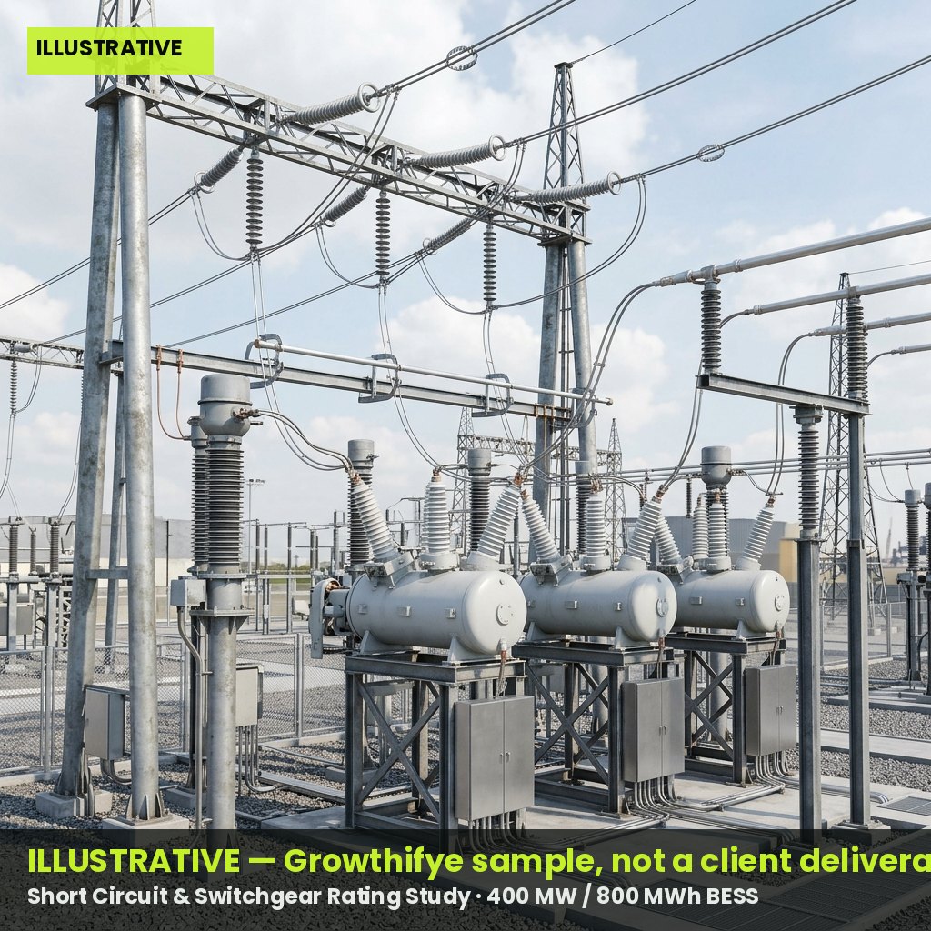
Short Circuit & Switchgear Rating Study
Fault current calculations at all critical buses to confirm switchgear, CT and breaker ratings for the evacuation scheme.
Sample excerpt · Fault Level Summary (3-Phase & Line-to-Ground) — illustrative figures
| Bus | 3-Phase Fault (kA) | L-G Fault (kA) | Existing Breaker Rating (kA) | Adequate? |
| POI 220kV Bus | 31.2 | 28.6 | 40 | Yes |
| Substation A 220kV | 33.5 | 30.1 | 40 | Yes |
| BESS 33kV Collector | 18.4 | 16.9 | 25 | Yes |
| Substation B 132kV | 22.7 | 20.3 | 25 | Marginal - review |
| Substation C 220kV | 29.8 | 27.2 | 40 | Yes |
- Marginal rating at Substation B flagged for utility discussion on upgrade
- Ratings cross-checked against manufacturer datasheets provided by client
Harmonic & Power Quality Assessment
THD and individual harmonic order analysis at the point of interconnection against IEEE 519 and CEA limits, with filter sizing recommendations if needed.
Sample excerpt · Harmonic Distortion Results at POI — illustrative figures
| Harmonic Order | Calculated (%) | IEEE 519 Limit (%) | Status |
| 5th | 1.8 | 4.0 | Pass |
| 7th | 1.2 | 4.0 | Pass |
| 11th | 0.9 | 2.0 | Pass |
| 13th | 0.6 | 2.0 | Pass |
| THD (Total) | 2.9 | 5.0 | Pass |
- No filtering required at rated BESS output based on inverter harmonic profile
- Recommend re-verification post final inverter selection
Outcomes
- Utility-approved evacuation scheme with defined point of interconnection and voltage level
- Switchgear and protection ratings confirmed before procurement, avoiding costly rework
- Documented compliance with CEA/IEEE grid code limits supporting faster interconnection approval
- Reduced project risk for lenders through independently validated stability and power quality findings
Questions clients ask
Why are system studies needed before detailed design?
They determine the evacuation voltage, route length and equipment ratings that detailed design depends on. Skipping this step risks redesign after utility review, adding months of delay.
Which software and standards do you use?
We use PSS/E or ETAP for load flow and stability modelling, and benchmark results against CEA regulations, IEEE 519 for harmonics, and applicable state grid codes.
How do these studies affect our interconnection agreement timeline?
A well-documented study package pre-empts utility queries, typically reducing interconnection approval cycles by 4-8 weeks compared to submissions without independent validation.