Detailed design
Detailed Design: Substation Layouts, Protection & Control, SCADA and Line Packages
We convert the approved system-study outputs and route corridor into fully engineered, construction-ready packages: substation general arrangement and layout drawings, protection & control (P&C) philosophy and schemes, SCADA/communication architecture, and transmission line design packages. Every drawing and schedule is issued at a quality suitable for tendering, statutory approval and construction, with clash-checked layouts and vendor-agnostic specifications that protect the client's interests through procurement.
Typical duration · 10-16 weeks depending on voltage class, number of bays and line length
Samples generated 05 Sept 2026, 11:27 pm ISTWhat happens in this step
- 01Finalise single line diagrams (SLDs), bus arrangements and bay layouts based on approved load flow, short circuit and stability study outputs
- 02Prepare substation general arrangement (GA), sectional and equipment layout drawings including clearances as per CEA/CBIP guidelines
- 03Develop protection & control philosophy, relay coordination studies, and P&C schematics for line, transformer and bus protection
- 04Design SCADA/RTU architecture, communication network topology (OPGW/fibre), and interface points with the utility's control centre
- 05Prepare transmission line design package: tower spotting, sag-tension calculations, foundation type selection and conductor/OPGW schedules
- 06Cross-discipline clash check and constructability review across civil, electrical and protection drawings
- 07Issue design packages for internal design review, statutory vetting, and procurement-ready issuance
What we need from you
- Approved system study report with fault levels, load flow and stability results
- Final route alignment / substation site survey and soil investigation data
- Voltage class, bay configuration and future expansion requirements from client
- Utility/DISCOM interconnection standards and protection coordination requirements
- Preferred equipment standards or approved vendor list, if any
- Right-of-way and statutory clearance status for line sections

Worked example (anonymised, illustrative)
Standalone BESS Interconnection Package · 400 MW / 800 MWh BESS with 220 kV pooling substation · Western India
Detailed design of a 220 kV pooling substation, associated P&C schemes and a 12 km double-circuit line package connecting the BESS to the state transmission utility's grid substation.
Sample deliverables from this step
Every sample below is analyst-written and anonymised for illustration — structure and depth mirror our real deliverables; figures and names are not from any client engagement.
 Illustrative · Growthifye-prepared
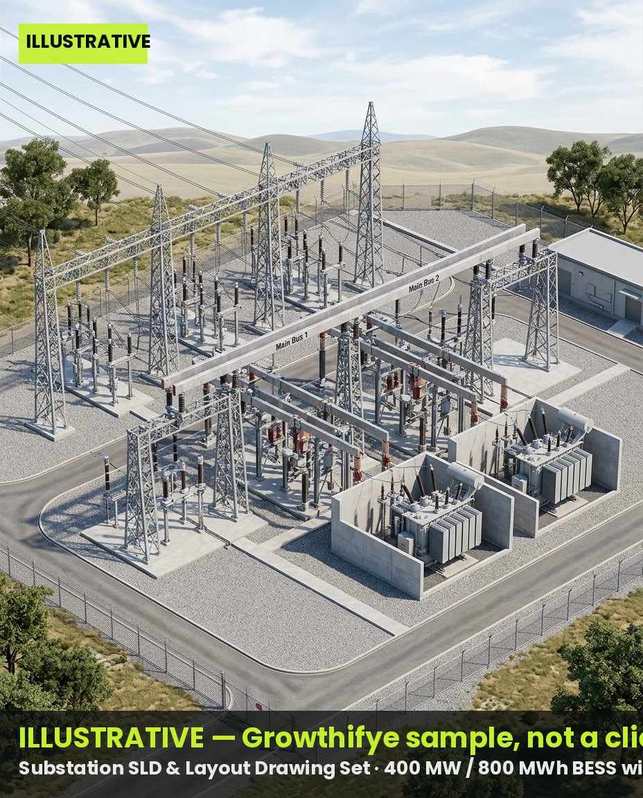
Substation SLD & Layout Drawing Set
Approved-for-construction single line diagrams, bay layouts, sectional views and equipment schedules for the 220 kV pooling substation.
Sample excerpt · Bay Schedule Extract — illustrative figures
| Bay No. | Voltage | Bay Type | Equipment | Rating | Status |
| B1 | 220 kV | Line Bay | CB, CT, CVT, Isolators | 220 kV, 40 kA | Issued for Construction |
| B2 | 220 kV | Transformer Bay | CB, CT, Isolators | 220 kV, 40 kA | Issued for Construction |
| B3 | 220 kV | Bus Coupler | CB, CT | 220 kV, 40 kA | Issued for Construction |
| B4 | 33 kV | BESS Feeder Bay | CB, CT, VT | 33 kV, 25 kA | Under Review |
| B5 | 220 kV | Spare Line Bay | CB, CT, CVT | 220 kV, 40 kA | Design Complete |
- Layouts follow CEA clearance and CBIP manual norms for 220 kV class
- Future 2-bay extension provisioned in the GA drawing
 Illustrative · Growthifye-prepared
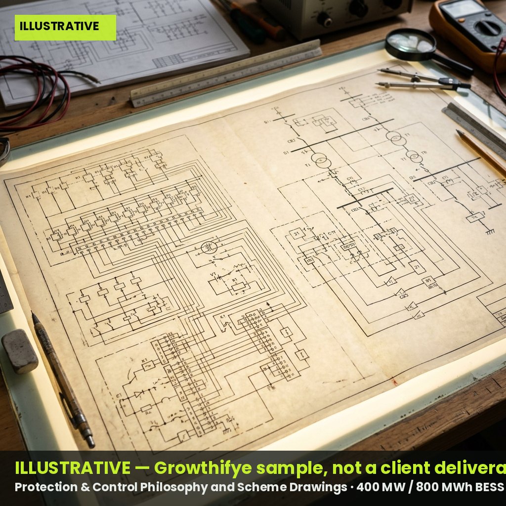
Protection & Control Philosophy and Scheme Drawings
Relay coordination study, P&C philosophy document and schematic drawings for line, transformer and busbar protection with redundancy analysis.
Sample excerpt · Protection Scheme Summary — illustrative figures
| Element | Primary Protection | Backup Protection | Relay Make/Class | Trip Time (typ.) |
| 220 kV Line | Distance (21) | Directional O/C (67) | Numerical, IEC 61850 | <100 ms |
| Power Transformer | Differential (87T) | REF (64) + O/C | Numerical, IEC 61850 | <50 ms |
| Busbar | Bus Differential (87B) | Breaker Failure (50BF) | Numerical, IEC 61850 | <30 ms |
| BESS Feeder | O/C + Earth Fault | U/V, O/V | Numerical, IEC 61850 | <150 ms |
- All relays specified with IEC 61850 GOOSE messaging for interoperability
- Coordination margins verified against utility's existing relay settings
SCADA & Communication Architecture Package
RTU/SCADA architecture, communication topology, and interface specification for data exchange with the utility load dispatch centre.
Sample excerpt · SCADA Interface Point List — illustrative figures
| Signal Group | Interface Type | Protocol | Data Point Count | Destination |
| Analog Measurements | RTU | IEC 60870-5-104 | 148 | State Load Dispatch Centre |
| Digital Status | RTU | IEC 60870-5-104 | 96 | State Load Dispatch Centre |
| Control Commands | RTU | IEC 60870-5-104 | 32 | State Load Dispatch Centre |
| BESS SOC/Power Setpoints | Local SCADA | Modbus TCP | 24 | Plant Control Room |
| Event/SOE Logs | Historian | OPC-UA | N/A | Plant Control Room |
- Redundant fibre communication path proposed via OPGW on the transmission line
- Cyber-security segregation per CEA guidelines included in the architecture
Transmission Line Design Package
Tower spotting plan, sag-tension calculations, foundation selection and conductor/OPGW schedules for the interconnecting line.
Sample excerpt · Tower Spotting Summary (Sample Section) — illustrative figures
| Tower No. | Type | Span (m) | Height (m) | Foundation Type | Terrain |
| T-14 | Tangent (A) | 320 | 24 | Pad & Chimney | Plain |
| T-15 | Angle (B) | 280 | 27 | Pyramid | Undulating |
| T-16 | Tangent (A) | 310 | 24 | Pad & Chimney | Plain |
| T-17 | Section (C) | 260 | 30 | Well Foundation | River Crossing |
| T-18 | Tangent (A) | 305 | 24 | Pad & Chimney | Plain |
- Sag-tension calculated for maximum design wind and temperature per IS 802
- River crossing tower designed with well foundation per soil report
Outcomes
- Construction-ready substation and line drawings accepted by the utility with minimal revision cycles
- Protection coordination validated against the utility's existing relay settings, avoiding nuisance tripping
- SCADA architecture pre-aligned with the load dispatch centre's interface standards, reducing commissioning delays
- Single integrated design package enabling faster, cleaner EPC tendering and vendor bid comparison
Questions clients ask
Do you design to the specific utility's standards or a generic template?
We design to the specific interconnecting utility's approved standards, drawing formats and protection philosophy, informed by prior engagements and publicly available utility manuals, then validate through the formal vetting process.
Can this step start before land/route approvals are finalised?
Preliminary layouts and SLDs can be advanced using the approved system study, but final GA drawings and line packages require confirmed site survey and route alignment data to avoid rework.
Who owns the IP in these drawings after handover?
All design deliverables, models and calculation files are handed over to the client with full ownership on completion of the engagement, for use in procurement and construction.