Route & site engineering
Route & Site Engineering: Optimised Corridors, Sound Foundations, De-Risked Substation Sites
We translate the approved evacuation and system-study outputs into a buildable transmission corridor and substation footprint. Combining satellite/LiDAR survey, tower spotting, geotechnical investigation and stakeholder mapping, this step delivers a route and site package that minimises land acquisition risk, forest/CRZ clearance delays and construction cost overruns before detailed design begins.
Typical duration · 8-14 weeks depending on line length and terrain complexity
Samples generated 05 Sept 2026, 11:26 pm ISTWhat happens in this step
- 01Desktop corridor screening using satellite imagery, forest/eco-sensitive zone maps and existing RoW data to shortlist 2-3 viable alignments
- 02LiDAR/DGPS or drone-based topographic survey along the shortlisted corridor to build a 3D terrain and vegetation model
- 03Tower spotting and profile plotting on the surveyed terrain to optimise span lengths, angle points and tower type selection
- 04Geotechnical investigation (trial pits/boreholes) at representative tower locations and the substation site to classify soil bearing capacity
- 05Substation site selection and comparison across candidate plots on land availability, flood/seismic risk, access road distance and grid-tie feasibility
- 06Stakeholder and statutory mapping - private land parcels, forest patches, water bodies, protected structures - with a preliminary crossing schedule
- 07Consolidated route alignment drawing, tower schedule and site selection memo issued for client sign-off before detailed design
What we need from you
- Approved system study report with confirmed voltage level, circuit configuration and indicative corridor
- Survey-of-India/satellite base maps and any prior RoW or land records available with the client
- Forest, wildlife sanctuary, CRZ and defence-restricted zone boundary shapefiles for the region
- Substation shortlist land parcels with revenue records/khasra maps, if already identified
- Access to site for topographic and geotechnical survey teams (local coordination/permissions)
- Client's tower design standard or preferred supplier catalogue (if pre-selected)
- Budget and schedule constraints influencing route length vs. land cost trade-offs

Worked example (anonymised, illustrative)
132 kV D/C Transmission Line & Switching Station · 50 MWac solar park evacuation, single circuit initially, D/C ready · Maharashtra, Western India
18 km greenfield 132 kV line connecting a solar park pooling substation to the nearest DISCOM switching station, routed through mixed agricultural land and a short forest patch requiring diversion approval.
Sample deliverables from this step
Every sample below is analyst-written and anonymised for illustration — structure and depth mirror our real deliverables; figures and names are not from any client engagement.
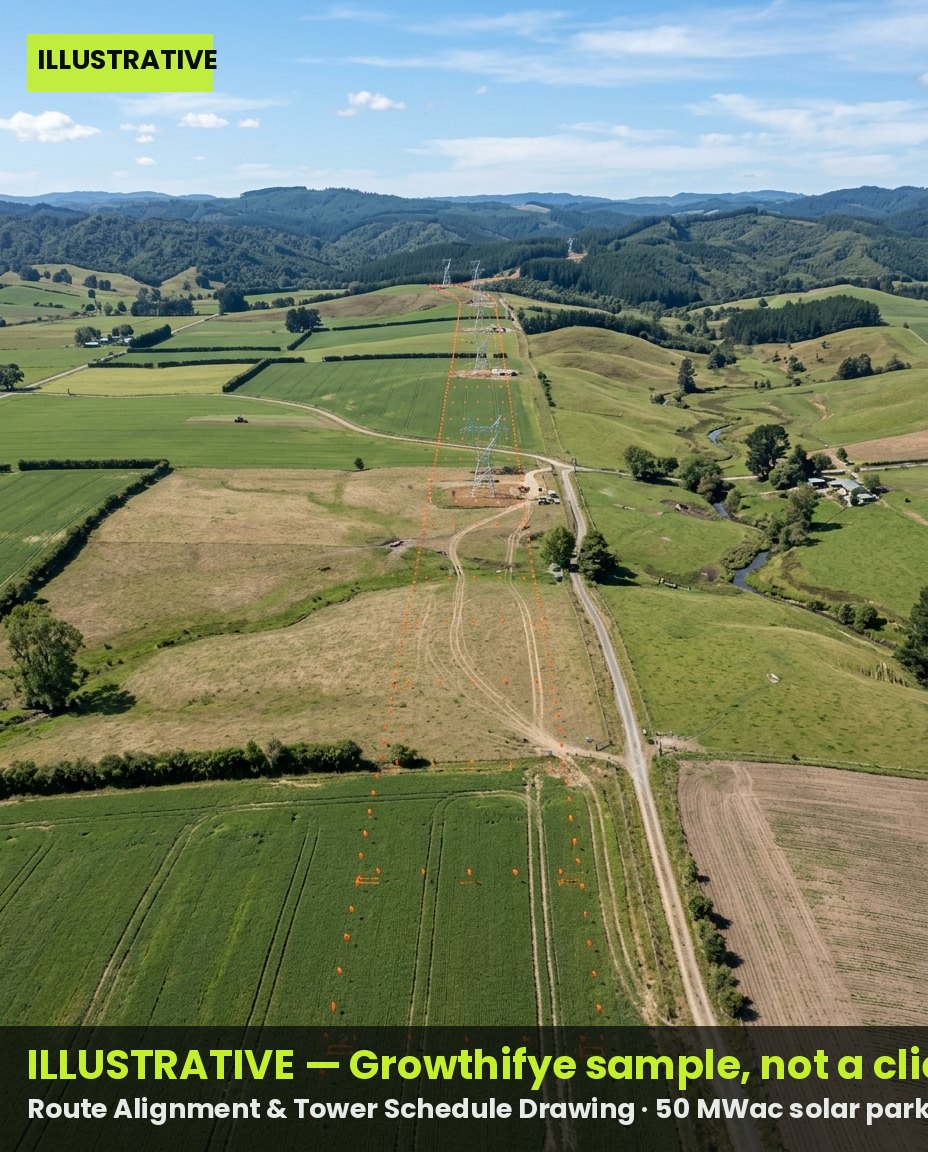 Illustrative · Growthifye-prepared
Route Alignment & Tower Schedule Drawing
Georeferenced plan-profile drawing showing final alignment, tower locations, span lengths, angle points and crossing details.
Sample excerpt · Tower Schedule Extract (Sample Section, Ch. 4.0-6.5 km) — illustrative figures
| Tower No. | Chainage (km) | Type | Height (m) | Span (m) | Deviation Angle | Soil Class |
| T-14 | 4.10 | Suspension DE | 24 | 310 | 0° | Class II (medium) |
| T-15 | 4.42 | Suspension DE | 24 | 320 | 2° | Class II (medium) |
| T-16 | 4.75 | Angle A0 | 27 | 290 | 18° | Class I (soft) |
| T-17 | 5.05 | Suspension DE | 24 | 305 | 0° | Class III (hard) |
| T-18 | 5.38 | Section Tower | 30 | 280 | 0° | Class III (hard) |
| T-19 | 5.68 | Suspension DE | 24 | 300 | 0° | Class II (medium) |
- Angle towers positioned to avoid two private orchards flagged during ground survey
- Final tower type selection to be validated in detailed design against loading standard
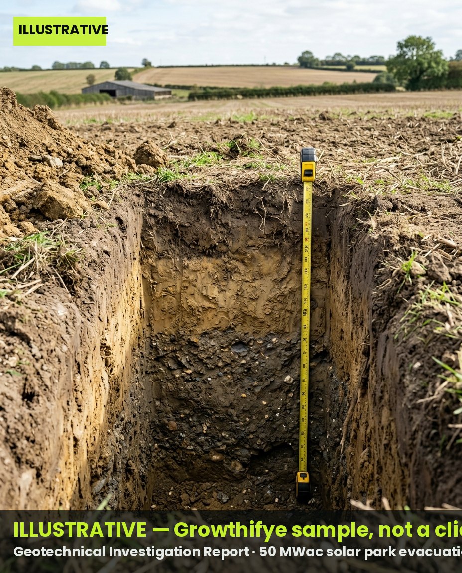 Illustrative · Growthifye-prepared
Geotechnical Investigation Report
Soil classification, bearing capacity and foundation recommendation for representative tower locations and the substation site.
Sample excerpt · Trial Pit Summary - Substation Site & Sample Towers — illustrative figures
| Location | Depth Investigated (m) | SPT N-Value | Soil Type | Bearing Capacity (t/m²) | Water Table (m) | Foundation Type Suggested |
| Substation Site | 6.0 | 22-28 | Silty sand | 18 | 4.2 | Raft/isolated footing |
| T-10 | 3.0 | 12-16 | Clayey silt | 12 | 3.5 | Under-reamed pile |
| T-16 | 3.0 | 6-9 | Soft clay | 8 | 2.1 | Pile foundation |
| T-25 | 3.0 | 30+ | Weathered rock | 35 | 6.0+ | Open footing |
- Soft clay stretch (T-15 to T-17) flagged for pile foundation cost premium in BoQ
- Substation site confirmed suitable for raft foundation without major ground improvement
Substation Site Selection Memo
Comparative evaluation of candidate substation plots against technical, statutory and cost criteria with a recommended site.
Sample excerpt · Site Comparison Matrix — illustrative figures
| Criterion | Site A (Recommended) | Site B | Site C |
| Land area available | 4.2 acres, single owner | 3.8 acres, 3 owners | 5.0 acres, government land |
| Distance to grid tie-in point | 1.2 km | 3.4 km | 0.8 km |
| Flood risk (100-yr contour) | Outside | Outside | Marginal, within buffer |
| Forest/CRZ clearance needed | No | No | Yes, minor patch |
| Estimated land cost | ₹1.4 Cr | ₹1.1 Cr | ₹0.9 Cr (lease) |
| Overall ranking | 1 | 2 | 3 |
- Site A recommended despite higher land cost due to single-owner acquisition and no forest clearance dependency
- Site C excluded primarily on clearance timeline risk to project schedule
Outcomes
- Land acquisition and forest clearance risks identified and quantified before detailed design commitment
- Optimised tower count and span design reducing overall line cost by minimising unnecessary angle points
- Geotechnically validated foundation strategy avoiding costly design changes during construction
- Substation site selection backed by a defensible, criteria-based comparison for internal and lender approval
Questions clients ask
How many alternative route corridors do you typically evaluate?
We usually screen 2-3 corridor options at desktop stage using satellite and statutory overlay data, then carry the most viable one or two forward to detailed ground survey before finalising a single alignment.
Do you handle forest and land acquisition clearances directly?
We identify clearance requirements, prepare supporting technical documentation and coordinate with the client's land/legal team, but statutory filing and approval remain the client's or their appointed agency's responsibility.
What happens if geotechnical results differ significantly from assumptions in the system study?
We flag material deviations immediately - such as unexpectedly soft soil requiring pile foundations - and reassess cost and schedule impact before proceeding to detailed design, avoiding downstream rework.