
Short-Circuit Levels in India 2026: RE Evacuation, ISTS Design and Grid Compliance
By Sudarshan Karweer · sudarshan@growthifye.com · +91 84510 99371 (Call / WhatsApp) · 2026-09-17
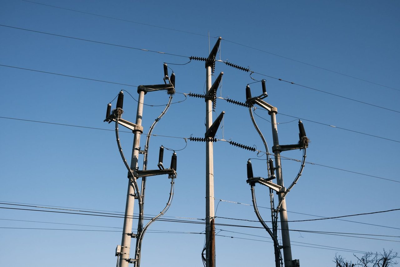
Photo: Matias Mango on Pexels
India’s rapid renewable-energy build-out has made transmission planning more complex than simple corridor availability. In 2026, one issue is becoming critical across high-renewable states and ISTS pooling nodes: short-circuit level management. As more substations, stronger grid links, synchronous generation pockets, STATCOMs, HVDC terminals and inverter-based resources connect into the same electrical area, fault currents can rise to levels that challenge existing switchgear, busbars, CTs, protection settings and substation expansion plans.
For developers, this is no longer a utility-only concern. A solar, wind, hybrid or RTC project can secure land, module supply and offtake visibility, yet still face delay if the evacuation node is nearing its fault-level limit or if a planned bay extension requires breaker upgrades across the yard. For lenders, high fault-level risk is now a bankability variable because it affects capex, commissioning schedule, outage coordination and the conditions in connectivity approvals.
This article explains how short-circuit levels influence RE evacuation in India in 2026, what standards and institutions matter, where costs tend to arise, and how project sponsors should approach studies and design choices early.
Why short-circuit levels matter more in India’s 2026 RE pipeline
A short-circuit level, often expressed in kA or MVA at a bus, indicates the magnitude of current that can flow during a fault. In practical terms, it determines whether the installed equipment at a substation can safely interrupt and withstand the fault duty.
This matters more in 2026 for five reasons:
- ISTS pooling substations in Rajasthan, Gujarat, Karnataka, Andhra Pradesh and Tamil Nadu are getting denser with renewable injections.
- Green Energy Corridor investments have strengthened networks, which is good for transfer capability but can increase fault contribution at specific nodes.
- Legacy substations built for lower fault levels are being expanded repeatedly through new bays rather than fully reconfigured.
- Urban and industrial load growth is pushing stronger interconnections between state networks and ISTS.
- Additional compensation and stability equipment can alter network strength and protection coordination.
A substation designed years ago with 40 kA or 50 kA breaker assumptions may now be operating closer to its interrupting limit under updated network configurations. In some EHV nodes, especially 220 kV and 400 kV yards around major renewable zones, planners are having to verify whether future-year fault levels remain within equipment capability after all approved and likely projects are included.
For developers, the implication is straightforward: available transformation capacity or a bay indication does not automatically mean technically feasible connectivity under all fault scenarios.
Where fault-level constraints show up in ISTS and state evacuation planning
In India, fault-level constraints can emerge at multiple voltage levels and planning interfaces:
- 220 kV state evacuation substations connecting large solar or wind clusters
- 400 kV pooling stations under central or state transmission utilities
- 765 kV ISTS nodes where multiple corridors converge
- Renewable energy zones with hybrid projects and storage sharing the same evacuation area
- Industrial open-access corridors where state and central network interactions are strong
Typical situations seen in 2026 include:
- New line addition improves evacuation but raises fault current at the receiving bus beyond breaker rating.
- A transformer addition solves thermal loading but worsens fault duty and busbar withstand requirements.
- Loop-in loop-out arrangements provide a quick connection path but complicate protection grading and breaker-duty checks.
- A node appears feasible in a preliminary connectivity discussion, but detailed short-circuit studies show the need for reactor insertion, network splitting or equipment replacement.
In high-growth renewable regions, this issue can change project economics materially. A developer expecting standard bay-extension cost may instead face a larger upstream scope if the utility requires fault-current mitigation or broader yard retrofits before connectivity can be energised.
The 2026 Indian regulatory and technical context
Short-circuit level planning sits across several regulatory and technical layers in India:
- CEA Technical Standards for Connectivity to the Grid
- CEA Regulations on Safety and Electric Supply
- Indian Electricity Grid Code and related grid operating requirements
- CERC connectivity framework and GNA-related implementation for ISTS access
- CTU/STU planning criteria and utility-specific design practices
- OEM equipment standards aligned to IEC/IS fault withstand and interrupting ratings
For an RE project connecting to ISTS or state transmission systems, the fault-level question usually appears during one or more of the following stages:
- Connectivity application review
- n- System-strength and network study by CTU/STU or appointed consultant
- Bay allocation and substation extension design
- Protection philosophy approval
- Detailed engineering and equipment rating validation
- Final commissioning readiness checks
Developers should also remember that fault level is not a static number. It depends on network topology, outage conditions, generation dispatch, in-service compensation devices, and future planned assets. The “as on date” value may be acceptable, while the “commissioning year with planned network” value may not be.
That distinction is especially important in India because many RE projects are awarded before all associated transmission elements are physically completed. A project can therefore enter a changing network context between award and synchronisation.
How fault-level studies are done for RE evacuation projects
A proper fault-level assessment is not a basic load-flow note. It should be integrated with the wider evacuation study package. In practice, developers and utilities typically evaluate:
- Three-phase fault current at the point of interconnection
- Single-line-to-ground and line-to-line fault levels where relevant for protection design
- Initial symmetrical current and peak making current duty
- Breaker interrupting capability versus calculated duty
- Busbar, isolator, CT and equipment short-time withstand limits
- Impact of all planned network additions by commissioning year and horizon year
- Sensitivity under N-1 or key outage topologies
- Contribution from nearby synchronous generation and large inverter-based plants as modelled
For large solar, wind, hybrid and storage projects, these studies should sit alongside load flow, transient stability, reactive power and harmonic checks. Growthifye’s Power system studies capability becomes relevant here because a fault-level result without corresponding equipment and protection implications is not enough for decision-making.
Key data inputs usually include:
- Single-line diagrams of the project and evacuation system
- Utility network model and planned augmentation list
- Transformer impedance and ratings
- Line parameters and sequence data
- Existing breaker and busbar ratings at the proposed substation
- Plant inverter or WTG short-circuit contribution characteristics as accepted by the utility model
- Compensation devices such as shunt reactors, series compensation, STATCOM/SVC and HVDC interaction assumptions where applicable
One common mistake is relying only on an early utility indication that a bus is “available.” Availability must be validated against the latest approved network base case and the expected commissioning timeframe.
Equipment and design consequences when fault levels are high
If calculated fault levels approach or exceed equipment ratings, the consequences can be significant. The issue is not just breaker replacement. It can trigger redesign across the substation.
Typical impacts include:
- Higher-rated circuit breakers, often moving from an existing installed rating to the next standard class
- Busbar strengthening or revised bus arrangement
- CT replacement if thermal or dynamic withstand is inadequate
- Protection setting revision and coordination study updates
- Current-limiting reactor installation in some cases
- Transformer selection changes depending on system configuration
- Phasing constraints for bay addition and outage planning
- Increased testing and commissioning complexity
At 220 kV and 400 kV levels, replacing breakers in an operating yard is rarely a trivial capex line item. It may require multiple planned outages, bus shutdown windows, civil modification, control wiring changes and re-approval of the protection scheme. In congested renewable zones, outage windows themselves can become a bottleneck.
This is why developers should assess whether a “cheaper” nearest substation is actually the least-cost option. A slightly farther node with lower fault duty and cleaner expansion margins may result in lower total project cost and lower schedule risk.
Where Growthifye supports clients on HV/EHV substation design, these trade-offs can be quantified early instead of emerging as a late-stage surprise.
What fault-level mitigation options are used in India
There is no universal remedy. The right approach depends on voltage level, ownership boundaries, fault margin, timeline and who bears the cost. In 2026, the most practical options in India include:
- Connecting at an alternate substation with lower fault duty
- Reconfiguring bus sections or splitting bus operation where operationally acceptable
- Installing current-limiting reactors at selected locations
- Replacing under-rated breakers and associated equipment
- Deferring or sequencing certain network additions if planning flexibility exists
- Shifting the point of interconnection from a heavily meshed node to a better-planned pooling arrangement
- Re-optimising transformation capacity distribution across nearby substations
Each option has cost and approval implications.
For example:
- A current-limiting reactor can avoid broader yard retrofits but introduces losses, voltage-drop considerations and layout implications.
- Breaker replacement can permanently solve the issue but may be capex-heavy and time-consuming.
- Bus splitting may reduce fault levels but can constrain operational flexibility and future transfer capability.
- Alternate-node connectivity may require longer transmission lines and additional RoW work, affecting both capex and schedule.
As an order-of-magnitude indication, the incremental cost impact from fault-level constraints can vary from a modest study-and-settings exercise to several crore rupees if multiple EHV breakers, CTs or bay equipment need replacement. For utility-scale projects, even a 2-6 month delay from redesign or outage dependency can have a larger financial impact than the direct electrical capex itself, especially where tariff discovery is tight and COD-linked revenues matter.
What developers, lenders and C&I buyers should do before locking evacuation
A practical 2026 checklist for stakeholders is as follows.
For developers:
- Seek latest fault-level data and not just transformer loading data for the proposed node.
- Ask whether values are current-state or future-year planning values.
- Verify breaker ratings, busbar configuration and expansion headroom at the interconnection substation.
- Integrate fault-level review into the same workstream as connectivity, bay design and protection approval.
- Compare at least two evacuation node options on total delivered-cost basis, not only line length.
For lenders:
- Treat interconnection technical clearance as distinct from generic transmission availability.
- Ask whether any upstream augmentation is needed because of fault-duty exceedance.
- Check who bears capex for utility-side upgrades and whether that is locked contractually.
- Examine outage dependency and commissioning-window risk.
For C&I consumers and open-access buyers:
- Understand that connectivity delay can affect supply start date, banking strategy and contracted energy profile.
- Ask the generator whether evacuation studies include fault-level validation and utility acceptance.
For utilities and policymakers:
- Prioritise transparent publication of planning assumptions at major renewable nodes.
- Use forward-looking fault-level maps at key 220/400/765 kV substations in high-growth RE zones.
- Align transmission bidding, bay planning and equipment standardisation with realistic 2030 renewable scenarios, not only current connected capacity.
This is also where integrated advisory matters. Connectivity decisions, substation engineering, Protection, control & SCADA, and commissioning planning should not be handled as isolated silos when fault levels are near limits.
The strategic takeaway for India’s RE evacuation market
In 2026, India’s transmission challenge is not only building more lines and substations. It is building connectable, operable and future-ready nodes. Rising short-circuit levels are a clear example of this shift. A project may have nominal access to the grid but still struggle to energise on time if fault-duty implications are identified late.
For renewable developers, the winning approach is early technical diligence on the exact interconnection node, future-year network condition and equipment rating margins. For lenders, fault-level risk deserves attention alongside land, module supply, counterparty and curtailment risk. For utilities, better transparency and proactive substation modernisation can reduce avoidable delays in RE integration.
The commercial message is simple: evacuation planning should move from “where is there a bay?” to “where is there a bankable, compliant and expandable interconnection?” In many cases, that one shift in framing can save months of delay and prevent avoidable capex escalation.
If your project needs support on transmission planning, substation engineering, connectivity risk review or utility-facing technical diligence, contact Growthifye’s advisory desk. Our team can help assess node feasibility, study fault-level exposure and structure a practical evacuation pathway for 2026 projects.
Explore Growthifye's related capabilities
This analysis connects directly to our advisory practice: Power system studies · HV/EHV substation design · Transmission line engineering · Protection, control & SCADA.
About the author

Chief Executive Officer, Growthifye — With over 23 years in management consulting, Sudarshan has taken businesses from concept to scale — building and scaling new-age digital and energy businesses.
- 23+ years in management consulting
- EY alumnus
- Led large-scale BESS programmes, capital raises and advisory mandates
Want this analysis applied to your project?
Talk to our team

