Engineer for constructability
Engineering that survives contact with the site — not the datasheet
Before a single container or panel is ordered, we stress-test the design against real site conditions: soil, access roads, monsoon drainage, local code clearances and how technicians will actually operate and maintain the asset for 20 years. This step catches the gap between a vendor's reference layout and what your specific site, climate and DISCOM interconnection actually require.
Typical duration · 4-6 weeks, run concurrently with detailed design
Samples generated 07 Sept 2026, 02:06 am ISTWhat happens in this step
- 01Cross-check vendor reference layouts against site topo survey, geotechnical data and drainage patterns
- 02Validate equipment sizing (PCS, transformers, cabling) against actual ambient conditions and site-specific auxiliary loads
- 03Review access roads, crane paths and lay-down areas against real construction logistics, not idealised plot plans
- 04Verify clearances, bay spacing and fire safety against applicable IS/CEA codes and state electrical inspectorate requirements
- 05Design O&M walkways, module-swap aisles and maintenance zones for 20-year operability, not just installation-day access
- 06Flag constructability risks in a formal register with mitigation options, costed where material
- 07Issue a sign-off package that procurement and construction teams work from — not a marketing-grade GA drawing
What we need from you
- Topographic and geotechnical survey of the site
- Tender/PPA technical schedule and interconnection single line diagram
- Local DISCOM/CTU interconnection standards and metering requirements
- Applicable IS codes, CEA regulations and state electrical inspectorate requirements
- Vendor reference designs and equipment datasheets (PCS, transformer, switchgear)
- Site access constraints (road width, load restrictions, monsoon working windows)
- O&M staffing and maintenance philosophy (in-house vs OEM AMC)

Worked example (anonymised, illustrative)
Standalone BESS constructability review · 400 MW / 800 MWh · Western India
A DISCOM-awarded standalone BESS project moved from vendor reference layout to a site-adapted design after review flagged drainage, crane-access and fire-clearance issues ahead of procurement.
Sample deliverables from this step
Every sample below is analyst-written and anonymised for illustration — structure and depth mirror our real deliverables; figures and names are not from any client engagement.
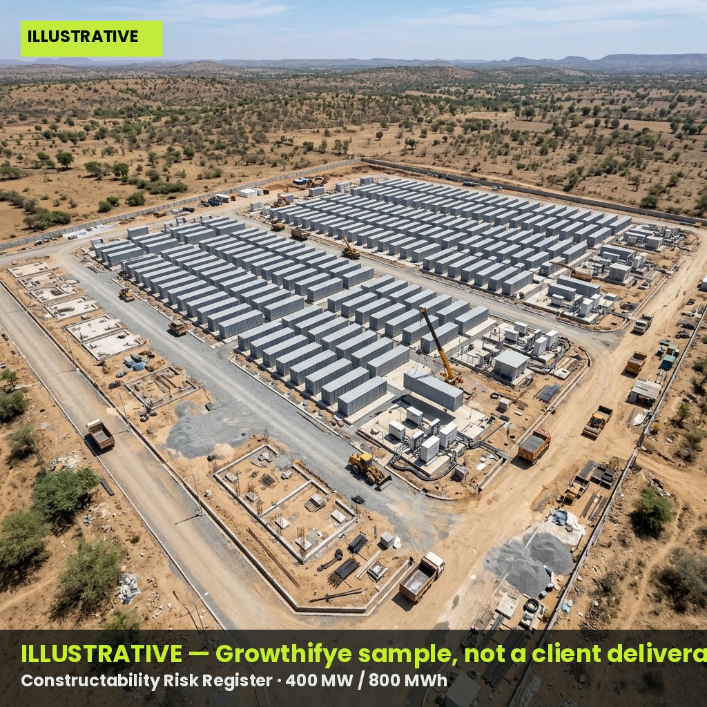 Illustrative · Growthifye-prepared
Constructability Risk Register
A structured log of every design element that fails against real site conditions, with impact and mitigation for each item, sequenced by procurement urgency.
Sample excerpt · Constructability Risk Register — Sample Extract — illustrative figures
| ID | Issue | Discipline | Impact if unresolved | Mitigation |
| CR-04 | 33 kV cable trench route crosses seasonal nullah | Civil/Electrical | 6-8 week monsoon delay risk | Reroute via elevated cable tray, add culvert crossing |
| CR-07 | Crane access width <4.5 m on north boundary | Layout | Crane cannot reach 12 of 48 skid positions | Widen access road to 6 m, relocate perimeter fence |
| CR-11 | Transformer bay spacing ignores IS 1646 fire clearance | Electrical/Safety | Non-compliance at CEA inspection | Increase bay pitch by 1.2 m, revise layout |
| CR-15 | O&M walkway width insufficient for stretcher evacuation | Safety/O&M | EHS non-conformance | Widen walkways to 1.2 m minimum |
| CR-19 | Container pad levels ignore natural drainage fall | Civil | Ponding risk in monsoon | Re-grade pad with 1:100 fall to storm drain |
- Register is scored by cost-to-fix now vs cost-to-fix after procurement lock-in
- Shared with EPC contractor and lenders' engineer for joint sign-off
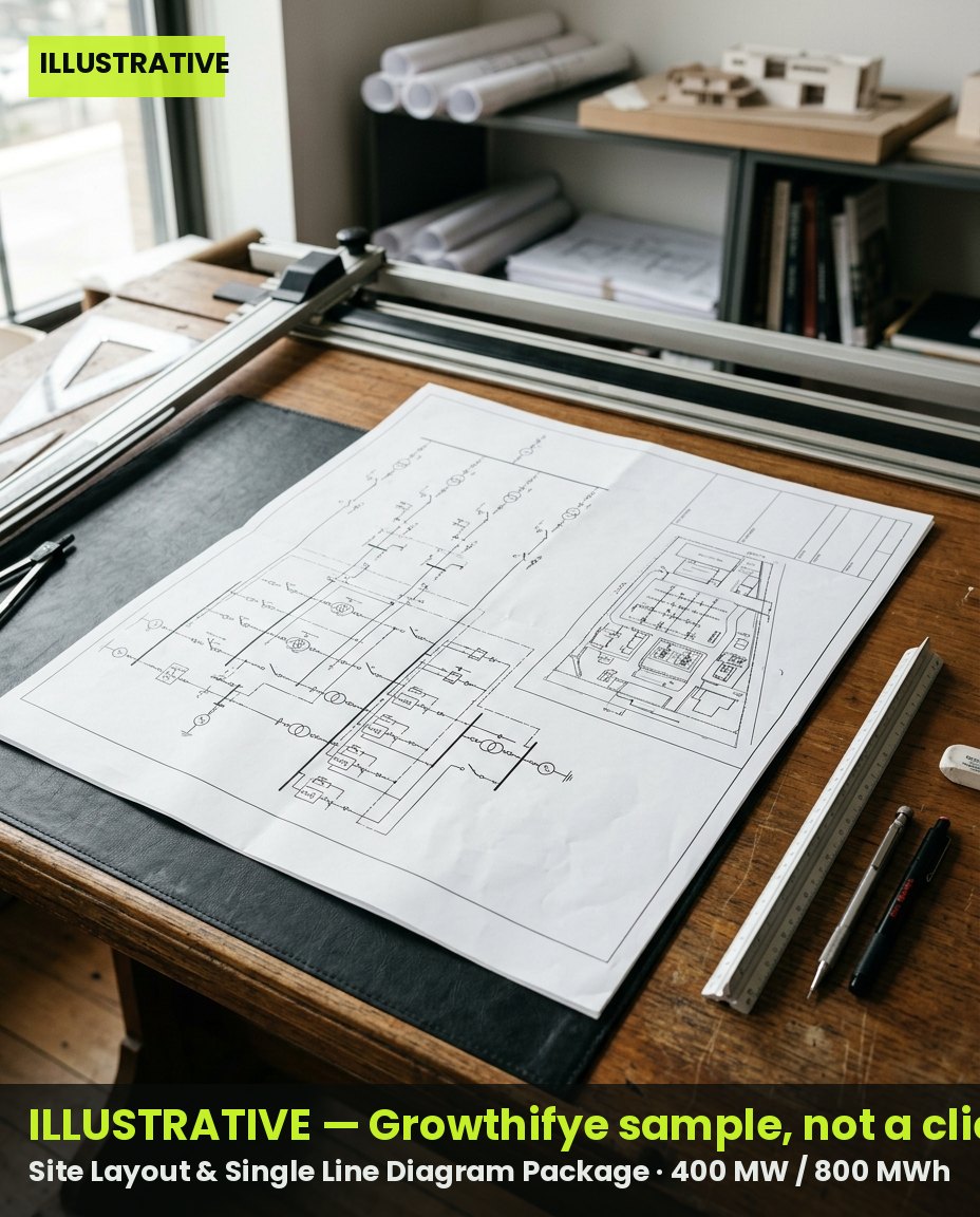 Illustrative · Growthifye-prepared
Site Layout & Single Line Diagram Package
Site-adapted general arrangement and electrical single line diagram, reconciled against survey data and code clearances, issued for procurement.
Sample excerpt · Single Line Diagram — Equipment Schedule Extract — illustrative figures
| Tag | Equipment | Rating | Qty | Location |
| T-01/02 | Power Transformer | 33/132 kV, 63 MVA | 2 | Substation yard |
| PCS-01 to 48 | Power Conversion Skid | 3.6 MW, 800 V DC | 48 | Battery blocks A-D |
| SWG-01 | 33 kV Switchgear Panel | 33 kV, 1250 A | 6 | Switchgear room |
| CB-01 | 132 kV Circuit Breaker | 132 kV, 2000 A | 3 | Switchyard |
| CT-01 | Current Transformer | 132 kV, 1200/1 A | 9 | Switchyard |
- Layout iterated three times against crane and cable-trench constraints before freeze
- Issued alongside a marked-up redline set showing changes from vendor reference design
Equipment Sizing & Interconnection Model
Engineering calculation set validating PCS, transformer and cable sizing against site ambient conditions and auxiliary loads, replacing generic vendor assumptions.
Sample excerpt · BESS Sizing & Auxiliary Load Summary — illustrative figures
| Parameter | Design value | Basis | Margin applied |
| Nameplate capacity | 800 MWh (DC) | Tender requirement plus degradation curve | 10% oversize for 20-yr EOL |
| PCS AC output | 400 MW | 1C discharge design point | — |
| Auxiliary load (HVAC + BMS) | 6.2 MW peak | Thermal model at 45°C ambient | 15% contingency |
| 33 kV feeder cable | 630 mm² Al XLPE | IEC 60502, derated for trench grouping | 1.2x thermal margin |
| Transformer capacity | 2 x 63 MVA | N-1 redundancy at full output | — |
- Model rerun against three ambient temperature scenarios before freezing sizing
- Used directly by procurement to write vendor technical specifications
O&M Access Design Memo
A short memo confirming maintenance zones, aisle widths and access provisions meet 20-year operability needs before construction locks in the layout.
Sample excerpt · O&M Access & Maintenance Zone Checklist — illustrative figures
| Zone | Requirement | Design response | Status |
| Container aisles | 3.5 m min for module-swap crane | Aisle width set to 4.0 m | Closed |
| Transformer bay | Oil containment plus 15 m fire clearance | Bunded pit, spacing per IS 1646 | Closed |
| Switchyard | Vehicle turning radius 12 m | Access loop road resurfaced | Closed |
| Perimeter | 24/7 security patrol route | 2.5 m patrol path, lighting at 30 m centres | Open — pending lighting design |
- Signed off jointly by O&M contractor and EPC before construction start
- Flags items still open at issue date for tracked closure
Outcomes
- Site-specific design issues identified before procurement, avoiding costly rework during construction
- O&M access and safety clearances built into the layout from day one, reducing lifecycle operating costs
- Equipment sizing validated against actual site conditions, not vendor default assumptions
- Constructability sign-off typically reduces change orders during EPC execution by 15-20%
Questions clients ask
Why not just use the EPC contractor's standard reference design?
Reference designs are optimised for factory cost and generic conditions, not your soil, drainage, access roads or local code interpretation. Adapting them upfront is far cheaper than redesigning mid-construction.
Does this add time to the project schedule?
It adds roughly 4-6 weeks upfront, run in parallel with detailed design, but typically saves more time downstream by avoiding rework, change orders and monsoon-season delays caused by unresolved site issues.
Can this be done before an EPC contractor is even selected?
Yes. We can run constructability review on competing bids to score technical quality pre-award, or on the appointed contractor's design post-award to refine it before procurement locks in.