India Solar SCB and MV Collection Design 2026: EPC, Losses, ALMM and Reliability
By Sudarshan Karweer · sudarshan@growthifye.com · +91 84510 99371 (Call / WhatsApp) · 2026-08-30
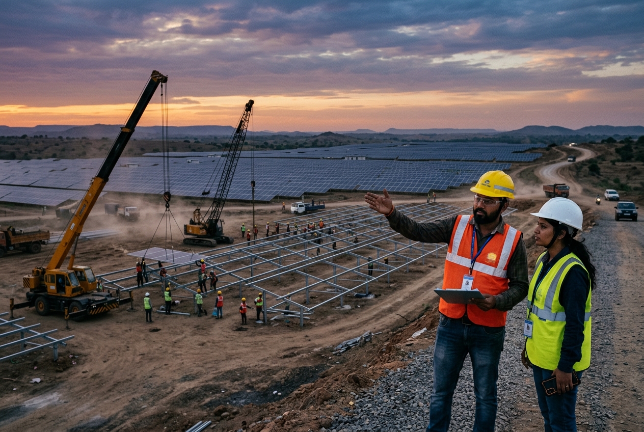
India’s solar market in 2026 is no longer just about module watts, inverter efficiency and tariff discovery. For many ground-mount and C&I plants, a meaningful share of avoidable yield loss, fire risk, delayed commissioning and capex overrun sits in the string combiner box (SCB), DC cabling and medium-voltage (MV) collection system. These packages look routine on paper, but in practice they determine how well a project survives India’s heat, dust, monsoon moisture, harmonic stress, rodent exposure and operating transients.
For lenders and asset owners, this matters because a 0.5% to 1.5% annual energy gap caused by poor collection-system design can wipe out the notional benefit of aggressive equipment pricing. For EPC contractors, SCB and MV decisions also affect construction speed, trenching quantities, land utilisation, cable losses, spares philosophy, shutdown planning and long-term O&M complexity. In 2026, these choices are further shaped by ALMM-linked procurement planning on the module side, domestic manufacturing expansion, tighter utility expectations on protection coordination, and growing lender scrutiny of as-built quality records.
This article focuses on a topic distinct from module, inverter, BOS and evacuation overviews: the detailed engineering and execution logic of SCB architecture and MV collection design for Indian solar projects in 2026.
Why SCB and MV collection design has become a board-level EPC issue
At first glance, SCBs and internal collection cables are commodity items. In reality, they shape five bankable outcomes:
- generation yield through DC and AC losses
- plant availability through fault isolation and maintainability
- fire and safety performance through protection, workmanship and enclosure integrity
- capex and schedule through metal content, trenching, terminations and testing effort
- dispute risk during handover through incomplete test records and undocumented design deviations
On a 50 MWac plant, the difference between disciplined and weak internal collection design can easily change capex by Rs 0.08 to Rs 0.22 crore/MW depending on topology, trench lengths, soil conditions, aluminium versus copper usage, and SCB density. More importantly, if the wrong design assumptions are locked in early, late-stage correction can become expensive. Replacing undersized DC homeruns, adding parallel MV runs, or reworking protection settings after utility observations can stall synchronisation and damage liquidated damages positions.
In C&I open-access projects, the commercial effect is sharper because every day of delay can mean foregone savings against grid tariffs that in 2026 often range from roughly Rs 6.0 to Rs 9.5/kWh depending on state, voltage level, banking rules and demand-charge structure. In utility-scale plants with discovered tariffs near or below the low-Rs 2.5 to Rs 3.2/kWh band in many cases, internal losses and availability penalties directly influence debt service coverage.
SCB architecture in 2026: what good design looks like
SCB design starts with module and string architecture, but it should not end there. In India, the most common failure modes still come from enclosure ingress, gland failures, incorrect fuse coordination, loose terminations, reverse-polarity mistakes, SPD deterioration, UV-damaged cable dressing and water accumulation near mounting locations.
A sound 2026 SCB design process should address:
- string count per SCB based on inverter MPPT architecture and maintenance philosophy
- fuse selection for actual Isc, bifacial gain assumptions and temperature effects
- Type II surge protection with proper earthing path and replacement indication
- IP65 or better enclosure performance with realistic site conditions, not catalogue assumptions alone
- UV-resistant cable glands, ferrules, lugs and labels suited for 25-year outdoor exposure
- anti-corrosion hardware in coastal, high-humidity or ammonia-prone locations
- thermal layout that avoids hot spots from compressed internal spacing
- structured drain and mounting details to reduce water ingress and mud splash
In many Indian sites, especially in Rajasthan, गुजरात, Maharashtra, Karnataka and Tamil Nadu, summer enclosure temperatures can exceed design assumptions if SCBs are mounted too close to reflected heat zones or without adequate ventilation logic. While over-venting can compromise ingress protection, under-venting can shorten SPD and fuse life. The answer is not generic vent drilling on site; it is engineered enclosure selection, verified heat-rise calculations and installation orientation control.
The industry also continues to debate centralised versus decentralised SCB placement. The practical answer depends on terrain, block size and cable economics:
- more SCBs closer to module tables can reduce string cable length and mismatch in routing
- fewer SCBs can reduce equipment count and inspection burden
- decentralised layouts often improve fault isolation but may increase civil supports and spares variety
- centralised layouts can simplify patrol routes but can increase DC homerun lengths and voltage-drop exposure
For high-capacity modules above 600 Wp, with bifacial gain assumptions of 5% to 12% depending on albedo and mounting, designers must revisit fuse and current-carrying calculations instead of mechanically carrying forward 2023 or 2024 standards. The old habit of using legacy margins without recalculating real operating currents is one reason SCBs run hotter than expected.
DC cable engineering: the hidden source of generation loss
A large number of Indian plants still under-model DC cable losses during bid stage and then attempt cost recovery by shrinking conductor sizes. That may help near-term capex optics, but it damages long-term energy output.
As a practical benchmark for 2026, many bankable designs target total DC losses in the broad range of 0.8% to 1.5%, while AC internal collection losses may sit around 0.6% to 1.2% depending on plant scale and topology. More aggressive loss targets are possible, but they must be justified against conductor cost and trench economics.
Good DC design should consider:
- actual route length, not straight-line drawing length
- temperature derating for Indian peak conditions
- grouping factor inside trenches or cable trays
- voltage drop under realistic operating current, not just STC assumptions
- mechanical protection near tracker torque tubes, sharp edges and ground transitions
- minimum bending radius and pull-tension control during installation
- rodent-resistant and UV-resistant sheath quality where relevant
The copper-versus-aluminium question is site-specific. Aluminium can reduce capex on larger runs, but termination quality, oxidation management and lug compatibility become critical. Many underperforming plants do not fail because aluminium was used; they fail because aluminium was adopted without disciplined connector engineering and torque control.
For developers, one useful tender-control measure is to specify not only conductor material and nominal size but also maximum permissible loss per feeder category, approved jointing philosophy, gland brands or qualification criteria, and compulsory thermography at pre-COD and post-monsoon stages.
This is where Growthifye’s Procurement & vendor management and QA/QC & HSE enforcement capabilities become commercially relevant: the technical specification must be translated into approved makes, inspection points, FAT expectations and site installation controls, otherwise the design intent is lost in execution.
MV collection system: topology, voltage level and reliability trade-offs
The MV collection network is the plant’s circulatory system. In Indian solar projects in 2026, the most common internal collection voltage levels remain 11 kV, 22 kV and 33 kV depending on plant size, utility interface and state practice. The choice is not cosmetic.
As plant size grows, higher internal voltage can reduce current, conductor size and losses, but equipment availability, switchgear standardisation, fault level, protection complexity and utility preferences also matter. For example:
- smaller C&I or captive plants may still favour 11 kV where utility and facility integration is straightforward
- mid-sized plants often evaluate 22 kV where cable optimisation is meaningful
- larger utility-scale blocks commonly move to 33 kV internal collection to control losses and feeder count
Ring versus radial topology is another important decision. Radial systems are cheaper and simpler, but a single feeder fault can isolate a larger block. Ring systems improve redundancy but raise capex and protection complexity. In India, many lenders accept radial topology for standard solar projects if fault segmentation, spare strategy and repair access are well demonstrated. However, where curtailment windows are narrow or monsoon restoration is difficult, selective use of ringed sections can be justified.
Designers should explicitly model:
- steady-state losses across seasonal generation profiles
- short-circuit levels at all RMUs and inverter transformer points
- earth-fault current path and touch potential
- voltage regulation under reactive-power operating scenarios
- harmonic contribution from inverter fleets and resonance risk
- trench derating due to multiple parallel MV circuits
Protection coordination remains a common source of late-stage observations from utilities and independent engineers. A typical weak point is copying generic relay settings without considering cable lengths, transformer impedance, earthing arrangement and inverter fault contribution. The result is nuisance tripping or non-selective operation.
For 2026 projects, commissioning packs should include verified protection coordination studies, relay setting files, primary and secondary injection records, and event-logger validation. These are no longer optional documents if the project is debt-funded or utility-interfaced at scale.
ALMM, domestic supply chains and what they change for collection design
ALMM mainly governs module procurement, but its downstream effect on SCB and collection design is real. Why? Because module dimensions, current ratings, bifaciality assumptions, connector compatibility and delivery sequencing all influence string design, SCB loading and cable schedules.
In 2026, with domestic manufacturing capacity deeper than in earlier years but still uneven across product classes, EPC teams must lock electrical design only after realistic module finalisation windows. A late change from one approved module family to another can alter:
- number of strings per inverter block
- n- SCB quantity and fuse ratings
- string cable lengths due to table geometry shifts
- DC/AC ratio assumptions and clipping profile
- spare philosophy for connectors and Y-branches
This is particularly important in projects linked to CFA schemes or DCR-linked compliance conditions, where the wrong procurement sequence can force redesign and documentation churn. While CFA structures differ by segment and programme, any scheme-linked project should maintain traceable BOM alignment between sanctioned design, procured equipment and as-built installation.
Practically, developers should insist that module finalisation, SCB ratings, inverter window and cable BOQ are frozen through a controlled design-release note rather than dispersed email approvals. That simple process discipline avoids many costly mismatches.
Construction and commissioning mistakes that keep recurring in India
Across states and site conditions, the same field issues keep appearing:
- mixed cable drum lots without traceability
- improper gland selection and gland plate workmanship
- cable trench backfill with stones or debris damaging sheath over time
- inadequate segregation between power and communication cables
- poor earthing continuity across SCB supports and metallic structures
- uncontrolled cable slack leading to abrasion and water traps
- skipped torque logs for SCB and RMU terminations
- no infrared thermography before reliability run
- incomplete insulation resistance and sheath integrity records
These are not minor defects. They directly affect COD readiness and first-year availability.
A robust commissioning protocol for SCB and MV systems should include:
- continuity, polarity and string current verification at block level
- insulation resistance testing as per approved method statements
- earth resistance and earth continuity measurement by location
- HV cable sheath testing where specified
- VLF or equivalent MV cable testing as applicable
- transformer ratio, winding resistance and vector-group verification
- relay testing, interlock checks and trip-circuit supervision
- SCADA mapping validation for feeder, SCB and inverter alarms
- thermal scanning under representative load
Owners should not accept a generic “all tests passed” certificate. They should require tagged records by feeder, SCB ID, cable drum or route segment, and equipment serial number. This is the only practical way to isolate latent defects after handover.
Firms with strong Testing, commissioning & handover discipline consistently reduce post-COD punch points because they treat documentation as part of quality, not an afterthought.
Cost, lender due diligence and how to write better EPC scopes in 2026
In a tight-tariff market, internal collection packages are often squeezed to protect bid competitiveness. But sophisticated lenders in 2026 increasingly examine whether low capex has simply deferred technical risk. Independent engineers now look beyond top-level single-line diagrams and ask for feeder-loss assumptions, cable derating logic, trench layouts, protection studies and approved makes.
For developers and C&I buyers, better EPC scope drafting can materially reduce later claims. Tender documents should clearly define:
- loss guarantees or design-loss caps for DC and internal AC systems
- approved or equivalent makes for SCBs, SPDs, glands, lugs and MV accessories
- minimum enclosure ratings and corrosion-protection requirements
- cable routing philosophy and trench construction standards
- mandatory FAT, routine test certificates and site inspection hold points
- spare parts list for SCB fuses, SPDs, cable terminations and RMU consumables
- as-built drawing, test dossier and tagging requirements at handover
- reliability-run criteria before PAC or FAC milestones
Commercially, even if such requirements add a few paise per watt upfront, they often produce a lower lifecycle cost. On many plants, recovering just 0.7% of annual generation through lower internal losses and better fault isolation has a stronger NPV effect than the savings from cutting corners on cables or SCB accessories.
For lenders, the due-diligence questions are straightforward:
- Are internal losses explicitly modelled and technically defensible?
- Does the design match actual module and inverter selections?
- Are protection studies project-specific or copied from another site?
- Are QA records sufficient to enforce warranty claims later?
- Is there a realistic spares and maintainability plan?
If the answer to these is weak, the plant may still achieve COD, but long-term reliability risk remains elevated.
What project sponsors should do now
In 2026, Indian solar sponsors should treat SCB and MV collection design as an energy-yield and finance issue, not a low-value electrical package. The right approach is simple:
- freeze module and inverter assumptions before final cable and SCB sizing
- optimise for lifecycle losses, not just initial copper or aluminium savings
- make protection coordination and test documentation non-negotiable
- align CFA or compliance-linked documentation with actual BOM and as-built records
- insist on field-quality controls that survive monsoon, heat and dust conditions
For utility-scale, open-access and large C&I plants alike, the collection network is where engineering discipline becomes bankability.
If you are structuring a new solar project, redesigning an underperforming internal collection system, or reviewing EPC scopes before tender, contact Growthifye’s advisory desk for a practical review of design, procurement, quality and commissioning strategy.
Explore Growthifye's related capabilities
This analysis connects directly to our advisory practice: Solar & hybrid plant EPC · BESS system integration · Balance of system & civil works · Procurement & vendor management.
About the author

Chief Executive Officer, Growthifye — With over 23 years in management consulting, Sudarshan has taken businesses from concept to scale — building and scaling new-age digital and energy businesses.
- 23+ years in management consulting
- EY alumnus
- Led large-scale BESS programmes, capital raises and advisory mandates
Want this analysis applied to your project?
Talk to our team