
India Data Centre Grid Connectivity 2026: Redundancy, STU/CTU Access and BESS
By Sudarshan Karweer · sudarshan@growthifye.com · +91 84510 99371 (Call / WhatsApp) · 2026-09-13
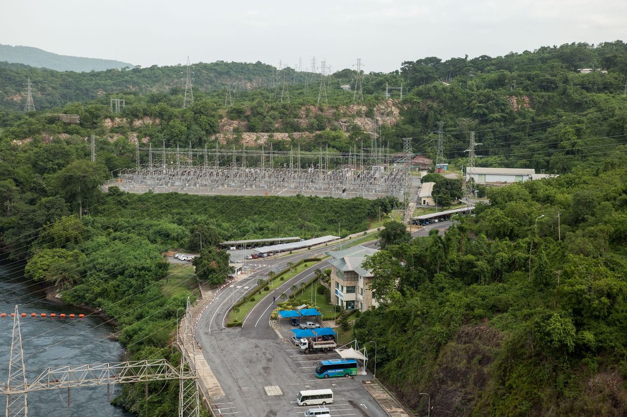
Photo: Andy Coffie on Pexels
India’s data centre market has spent the last two years discussing renewable procurement, hourly matching and tariff optimisation. In 2026, a different bottleneck is becoming decisive: getting enough firm electrical connectivity, with the right redundancy architecture, on a realistic construction schedule and with a bankable operating-cost profile.
For hyperscale and colocation operators, the practical question is no longer only “what power price can we contract?” It is “can we secure 60 MW, 120 MW or 300 MW with N-1 or better resilience, acceptable fault levels, black-start logic, and an expansion pathway that does not strand capital?” For lenders and investors, grid access has moved from a permitting line item to a critical diligence theme because energisation delays can destroy revenue ramp-up assumptions.
This article looks at India’s 2026 data centre grid-connectivity landscape through a practitioner lens: STU versus CTU interconnection choices, substation topology, redundancy design, approval sequencing, key charges, on-site BESS integration, and the commercial implications for site selection. It is intentionally different from discussions on 24/7 CFE contracting or open-access structures. The focus here is the physical and regulatory path to getting megawatts to a mission-critical campus.
Why grid connectivity is now the gating item
The first driver is load size. A modern AI-heavy or high-density data centre campus in India can begin with 30-50 MW IT load and scale to connected electrical capacities well above 100 MW once cooling, redundancy and growth are included. Depending on PUE, a 50 MW IT block at a PUE of 1.35 implies about 67.5 MW total facility load; at PUE 1.50, it becomes 75 MW. Multi-building campuses can quickly exceed the spare capacity available at nearby urban substations.
The second driver is location concentration. Mumbai Metropolitan Region, Chennai, Hyderabad, Pune, NCR and Bengaluru continue to attract most deployments because of cable landing stations, fiber ecosystems, enterprise demand and cloud availability zones. The result is local congestion in transmission corridors, longer bay-allocation timelines and more scrutiny on upstream evacuation margins.
The third driver is reliability expectation. Enterprise colocation contracts still expect very high uptime, but discom and transmission-system realities include planned outages, protection trips, transformer constraints, voltage excursions and restoration delays. Even where annual grid availability is nominally strong, the shape and duration of interruptions matter far more for a data centre than for ordinary C&I loads.
That is why connectivity planning now has to combine utility interface engineering, internal electrical architecture, and storage-backed ride-through. Growthifye’s Grid connectivity & redundancy work typically starts with this integrated view, not with a single-application filing to the utility.
STU versus CTU: how to choose the interconnection path
In 2026, most Indian data centres below roughly 80-100 MW contracted demand still evaluate state transmission utility connectivity first, particularly where a 220 kV or 110/132 kV node is nearby and the state framework is administratively smoother than a central-grid route. But that default is not always optimal.
A practical STU-versus-CTU screening should evaluate at least six factors:
- Required initial demand and ultimate campus demand
- Distance to the nearest suitable STU and CTU substations
- Available transformation margin and bay availability
- Reliability record of the local discom and transmission corridor
- Timeline certainty for approvals and energisation
- Ability to create dual independent incomers from electrically distinct sources
STU connectivity often offers shorter physical distance and easier state-level coordination, especially for loads in established industrial belts. However, the local network may have lower fault tolerance to large step-load changes, more dependence on a single upstream node, or limited room for future expansion.
CTU connectivity starts to make more sense when the project is very large, when the state network is congested, or when sponsors need stronger perception of supply robustness for hyperscale customers and lenders. A CTU-linked design may also align better with a broader energy strategy if the campus plans diversified sourcing, including interstate renewable delivery and large BESS-backed RTC arrangements. The trade-off is usually longer development lead time, more complex interconnection studies and potentially higher initial capex for dedicated transmission assets.
In several 2026 site screens, the decisive issue is not nominal voltage level but source independence. Two 220 kV feeders from the same upstream transformation pocket do not provide the same resilience as two feeds that separate early enough in the network to survive a transformer or busbar event. Data centre operators should therefore insist on single-line diagrams up to a meaningful upstream level, not just a generic utility assurance of “dual source”.
What redundancy really means for a data centre campus
Many projects describe themselves as 2N-ready or N+1-capable, but utility-facing redundancy is frequently less robust than the internal UPS and generator architecture. The weak point is often the grid interface.
For a campus-scale Indian data centre in 2026, good practice usually means:
- Two utility incomers that are physically and electrically independent to the maximum practical extent
- Separate transformer banks or separate bays, not just two breakers on a common constrained bus
- Protection coordination reviewed for DG, BESS and utility interaction
- Defined black-start and islanding philosophy, even if continuous island operation is not intended
- Sufficient on-site storage or generation to bridge transfer times and external restoration uncertainty
This matters because utility outage events are not binary. The real-world sequence may involve a voltage sag, feeder trip, unsuccessful auto-reclose, partial restoration, then manual switching. If the facility relies entirely on diesel generators for every disturbance, fuel logistics, emissions compliance and maintenance cycling become material operating issues. On-site BESS can materially improve this picture.
A 20-40 MW / 20-80 MWh BESS will not replace long-duration backup generation for most large campuses, but it can do three valuable things:
- Provide instantaneous ride-through and reduce transfer stress on critical loads
- Cover short and medium-duration grid disturbances that would otherwise trigger diesel starts
- Support demand management, reactive support and power-quality performance at the point of interconnection
For urban campuses facing strict local air-quality scrutiny and acoustic constraints, using battery storage to avoid frequent DG starts during momentary-to-short outages has become a strong operating case, not only a sustainability narrative. This is one reason On-site generation & BESS is moving from “nice to have” to core electrical design.
Approval sequence, land constraints and realistic timelines in 2026
A common mistake in board-level project schedules is treating power approval as a parallel workstream that will somehow close before fit-out. In reality, the connectivity sequence often governs the critical path.
A realistic sequence includes:
- Load forecast freeze for phase 1 and phase 2
- Preliminary utility engagement with substation-capacity check
- Application for connected load and demand sanction
- Interconnection and protection studies
- Land and right-of-way review for dedicated line if required
- Bay allocation, substation augmentation approval or dedicated GIS/AIS plan
- Electrical inspectorate approvals and testing
- Synchronisation, trial operation and final energisation
For large sites, 12-18 months from serious utility engagement to dependable energisation is not unusual, and complex cases can run longer. If a new bay, transformer augmentation or dedicated 220 kV line is required, timelines can extend further depending on state processes, forest or highway crossings, and procurement of major equipment.
Land-side design also matters. GIS substations reduce footprint but increase equipment cost; AIS can be cheaper per bay where land is available but often fails urban fit constraints. In Mumbai, Chennai and NCR micro-markets, land economics can make compact high-voltage design financially rational even when electrical capex appears higher on paper.
Developers should also recognise that utility letters of comfort are not equivalent to sanctioned capacity. Lenders increasingly ask whether bay allocation is formal, whether upstream augmentation is funded, and whether energisation dependencies sit with the project company or the utility.
The charge stack: what actually hits project economics
Power cost for a data centre is not just the energy tariff. Grid-connectivity choices affect both upfront capex and recurring network charges.
Depending on the state and voltage level, projects may face combinations of:
- Service connection and supervision charges
- Dedicated line capex from the nearest substation
- Bay-extension or substation-augmentation contributions
- Security deposit and metering costs
- Demand charges based on sanctioned or billing demand
- Transmission and wheeling charges where applicable
- Cross-subsidy and additional surcharge in specific procurement structures
- Reactive energy penalties or low power-factor penalties
For directly supplied embedded loads, the recurring burden often comes through contracted-demand structure and maximum-demand ratchets. If the campus over-contracts too early, it may carry avoidable fixed charges before server halls ramp. If it under-contracts, it risks penalties and delayed customer onboarding.
As a simple example, a campus taking 80 MVA sanctioned demand with a fixed or demand charge of even Rs 250-450 per kVA per month is exposed to roughly Rs 2.0-3.6 crore per month of demand-linked cost before energy consumption is counted. The exact number varies by state and tariff order, but the planning implication is clear: phase-wise demand sanctioning and commissioning logic matter.
This is where Load & reliability engineering intersects with commercial strategy. Good planning can stagger transformer installation, align chiller and UPS deployment with shell occupancy, and reduce idle contracted capacity without compromising customer delivery commitments.
Where BESS changes the grid-connectivity business case
In 2026, the most sophisticated data centre power strategies do not ask whether BESS is a substitute for the grid. They ask how BESS can reduce the cost and risk of obtaining and using grid connectivity.
There are four main use cases.
First, BESS can shave short-duration demand spikes, especially during plant transitions, reducing stress on utility interfaces and potentially lowering peak billing demand where tariff rules permit economic capture.
Second, BESS can improve commissioning flexibility. A campus waiting for full second-source readiness may still be able to commission certain blocks safely if the battery provides bridging support and operating envelopes are carefully defined. This is not a substitute for contracted redundancy, but it can accelerate revenue in tightly managed cases.
Third, BESS can defer portions of internal electrical capex. If the battery supports transfer events and short-duration peaks, some assets can be sized or phased more efficiently, especially where initial occupancy is well below full build-out.
Fourth, BESS can support power quality at the interconnection point. Fast inverter response helps with voltage support, ramp smoothing for on-site solar if present, and coordination with active harmonics mitigation and EMS controls. The exact design depends on utility interconnection conditions and protection philosophy.
Typical economic evaluation in India should compare battery capex and replacement assumptions against:
- Avoided DG runtime and maintenance
- Reduced diesel consumption and logistics burden
- Lower outage-induced SLA exposure
- Possible reduction in peak demand cost
- Better utilisation of contracted capacity
- Deferred internal infrastructure capex
The answer will vary by state tariff, outage profile and customer SLA structure. But for many 20 MW-plus campuses, a storage-led reliability layer is now easier to justify than in 2023 or 2024 because outage costs, density requirements and grid-interface complexity have all increased.
Site-selection implications for developers and lenders
The biggest strategic mistake is choosing a site primarily on land cost or fiber adjacency, then trying to “solve power later”. In 2026, power-first site selection is often the correct framework.
A strong site screen should rank locations on:
- Distance to multiple suitable high-voltage substations
- Upstream source diversity and historical outage behavior
- Substation expansion feasibility and right-of-way practicality
- Local discom responsiveness and tariff trajectory
- Water and cooling constraints that affect electrical load growth
- Probability of adding renewable and storage assets later
For lenders, diligence should test whether the project has:
- Sanctioned demand matched to realistic ramp assumptions
- Documentary evidence of source redundancy, not only sponsor statements
- Capex provision for dedicated line, bay and protection systems
- A credible strategy for outage bridging and black-start sequencing
- Sensitivity cases for energisation delay and partial-load operations
Policymakers and utilities also have a role. If states want to attract data centre investment, they need designated high-load digital-infrastructure zones with pre-planned substation capacity, faster bay-allocation decisions, and transparent service standards for mission-critical loads. Standardised procedures for large-demand consumers can materially shorten investment cycles.
A 2026 decision framework for data centre operators
For Indian data centre sponsors, the practical decision framework is straightforward.
- Start power diligence before land lock-in, not after
- Model full-campus demand, not just phase-1 connected load
- Test true source independence on the network one-line
- Compare STU and CTU routes on time certainty, not just nominal charges
- Size BESS around outage profile, transfer philosophy and tariff structure
- Align connectivity design with occupancy ramp and customer SLAs
- Document all utility assumptions for lender and customer diligence
The winning projects in 2026 will not simply have cheaper power. They will have faster and more bankable access to reliable power, with a grid architecture that can scale from first megawatt to full campus build-out without repeated redesign.
For a sector where every month of delayed energisation can mean lost rack revenue and strained customer commitments, that is the difference between an attractive business case and an expensive lesson.
If your team is evaluating a new campus, expansion block or utility-interface redesign, contact Growthifye’s advisory desk. We help data centre sponsors, investors and operators structure bankable connectivity strategies across utility approvals, redundancy architecture, BESS integration and execution planning.
Explore Growthifye's related capabilities
This analysis connects directly to our advisory practice: Load & reliability engineering · 24/7 clean power contracting · Grid connectivity & redundancy · On-site generation & BESS.
About the author

Chief Executive Officer, Growthifye — With over 23 years in management consulting, Sudarshan has taken businesses from concept to scale — building and scaling new-age digital and energy businesses.
- 23+ years in management consulting
- EY alumnus
- Led large-scale BESS programmes, capital raises and advisory mandates
Want this analysis applied to your project?
Talk to our team

