India Data Centre Grid Connection Strategy 2026: Redundancy, ISTS and N-1 Design
By Sudarshan Karweer · sudarshan@growthifye.com · +91 84510 99371 (Call / WhatsApp) · 2026-09-13
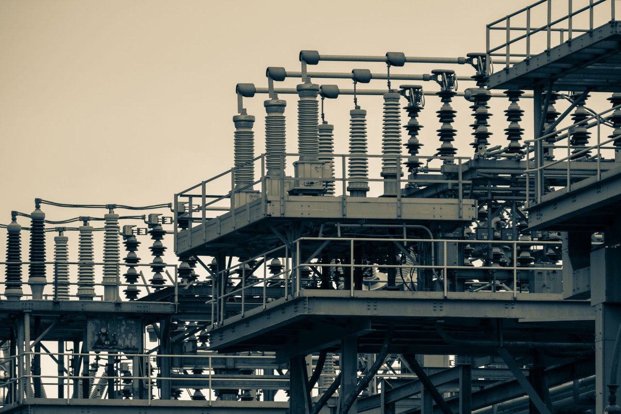
Photo: _ Whittington on Pexels
India’s data-centre power conversation often starts with renewable procurement, open access and battery sizing. In practice, the first make-or-break decision is grid connection architecture. A well-priced RTC contract is of limited value if the intake substation, utility interface, bay allocation, right-of-way, protection philosophy or redundancy design cannot deliver power on time and at the required availability.
For India’s data-centre developers in 2026, the grid-connection question has become more strategic, not less. IT loads are rising faster, campus-style developments are moving to 100 MW to 300 MW phases, and state-level connection processes remain uneven. At the same time, transmission utility scrutiny has increased around short-circuit contribution, reactive power, relay coordination, harmonic performance and fault ride-through. Add to that the need to integrate diesel backup, modular UPS blocks, on-site BESS and future renewable open-access imports, and the electrical single-line diagram becomes a financing issue as much as an engineering one.
This article looks at a topic distinct from contracting or energy attributes: how to design and sequence data-centre grid connectivity in India in 2026, with a focus on redundancy, voltage selection, ISTS versus state network access, substation planning, timelines, costs and lender-relevant risk controls.
Why grid connectivity is now a board-level issue
India’s large data-centre clusters are no longer dealing with 5 MW or 10 MW office-park style loads. In Mumbai Metropolitan Region, Chennai, Hyderabad, Pune, NCR and Bengaluru per-site contracted demand can move quickly from 30 MW in phase 1 to 80 MW to 150 MW as halls are commissioned. The consequence is simple: connection design choices made for early load can constrain later growth.
Three 2026 realities are driving this:
- Urban receiving substations in key data-centre corridors are capacity constrained, especially at 110 kV, 132 kV and 220 kV nodes.
- Bay availability, land access for line entry and terminal equipment lead times are now material schedule risks.
- Utilities are less willing to accept loosely specified redundancy claims; they want clear sanctioned demand, import/export logic, relay settings and DG/BESS operating modes.
For investors and lenders, the result is that connection readiness has become as important as land title and offtake visibility. A project that has land and customer interest but no credible utility tie-in path may be 9 to 18 months behind its commercial target date.
Choosing the right voltage level: 33 kV, 110/132 kV or 220 kV
There is no universal answer, but there are practical thresholds.
For smaller edge or enterprise facilities, 33 kV may still work, especially in states where the distribution company can offer dual independent feeders from separate source substations. But once IT plus mechanical load begins pushing facility demand beyond roughly 20 MW to 25 MW, 33 kV can become operationally tight. Feeder outages, fault levels, transformer sizing and expansion flexibility become concerns.
For medium and large campuses, 110 kV or 132 kV is often the practical starting point. At this level, data-centre operators can usually secure better transfer capability, lower technical losses and more credible redundancy pathways. In some states, 132 kV also sits at a useful regulatory boundary where process ownership shifts from the distribution utility toward the state transmission utility, improving network robustness but often adding approval layers.
At 220 kV, the logic is generally for larger campuses, multi-building expansions or where the nearest lower-voltage network is congested. 220 kV intake can make strong sense if ultimate site load is expected above 80 MW to 100 MW, or if future integration of substantial open-access imports and on-site BESS is planned. The trade-off is higher terminal capex, larger land requirement, more complex protection schemes and longer implementation timelines.
In 2026 market terms, developers should compare at least four cost buckets, not just tariff:
- Dedicated line and bay capex
- Utility deposits, supervision and connection charges
- Internal substation and transformer capex
- Time-to-energisation cost, including delayed revenue from uncommissioned white space
In several metro-adjacent locations, the revenue impact of a 6-month energisation delay can exceed the savings achieved by choosing a lower-capex but constrained voltage option.
Redundancy design: what N-1 really means at the utility interface
Data-centre brochures use terms like N, N+1 and 2N freely. Utilities do not. They evaluate source redundancy, feeder routing, bus configuration and transfer logic physically, not conceptually.
For Indian grid-connected data centres in 2026, a credible external power redundancy strategy should answer five questions:
- Are the two incoming sources electrically independent or only two feeders from the same upstream bus?
- Do the feeders share towers, trenches, ducts or terminal gantries at any point?
- Is the upstream source substation itself single-transformer vulnerable?
- Can protection isolation on one incomer occur without tripping the second source?
- What is the tested transfer time from one source to the other under utility and internal fault scenarios?
Many “dual source” schemes fail the first two tests. Two feeders from the same grid substation may improve maintainability but not true contingency resilience. Likewise, separate utility feeders sharing the same cable trench for the last 500 metres are not route-diverse in any meaningful risk sense.
A practical approach is to define three layers of redundancy:
- Network-source redundancy: separate upstream grid sources or substations
- Route redundancy: physically diverse line or cable path to site
- On-site transformation and bus redundancy: independent transformers, sectionalised buses and selective coordination
This is where Growthifye’s Grid connectivity & redundancy work matters. The aim is not to overspend on gold-plated architecture, but to identify the lowest-cost configuration that actually survives realistic failures, including bus faults, transformer outages, cable joint failures, relay mis-operations and maintenance isolation.
ISTS versus state network access for data-centre campuses
As data centres procure more renewable and hybrid power through open access, the connection architecture can no longer be planned only around local utility import. The site may need to receive power linked to state transmission or ISTS-connected generation, either physically through open-access scheduling or contractually through supply arrangements shaped around interstate generation.
In 2026, the ISTS-versus-state question matters for three reasons:
- Charges and waivers differ depending on project type, location and scheduling pathway.
- Curtailment and congestion risks are not identical across state and interstate corridors.
- Metering, scheduling and accounting complexity rises when multiple sources feed the same data-centre load profile.
For most data-centre operators, direct connection strategy is still state-network led, because the load is fixed in one state and retail supply obligations remain local. But for large campuses with major open-access procurement, transmission interface studies should evaluate:
- Whether the state node has enough import headroom during evening peaks
- Whether renewable-rich source states create shape or congestion stress in the delivery path
- Whether future expansion could justify higher-voltage intake to preserve sourcing flexibility
The point is not that every data centre should target ISTS-linked architecture. It is that connection design and power-sourcing strategy should be modelled together. A weak delivery node can erode the value of a well-negotiated clean-power portfolio.
Substation, protection and control design choices that affect uptime
The most common mistake in early-stage planning is treating the utility interconnection as a civil-and-electrical package to be optimised late. In reality, the protection and controls philosophy should be frozen early, because it drives utility approval, OEM selection, SCADA integration and commissioning sequence.
Key 2026 design considerations include:
- Bus configuration: single bus, single bus with sectionaliser, double bus or breaker-and-a-half depending on scale and uptime requirement
- Transformer philosophy: multiple smaller units may improve maintainability, while fewer larger units may lower capex but increase common-mode risk
- Relay coordination: utility relays, transformer differential, busbar protection, feeder relays, synch-check and under-frequency logic must be coordinated with UPS and DG response
- Reactive power management: data-centre load is dynamic; capacitor banks, SVGs or STATCOM-like solutions may be required depending on voltage level and utility code
- Black-start and restoration logic: post-outage sequencing matters when chillers, pumps, UPS blocks and battery systems all seek to recover simultaneously
Where on-site storage is planned, On-site generation & BESS should not be added as an afterthought. BESS can help with transition management, ramp control, limited peak shaving and short-duration ride-through support, but it does not replace sound external-source redundancy. A 20 MW / 40 MWh system may help bridge transfer events or reduce demand spikes, yet it will not solve a fundamentally weak utility intake design for a 100 MW campus.
The other increasingly important layer is controls integration. An Energy management systems architecture should sit above the utility interface, DG plant, UPS estate, HVAC major loads and BESS dispatch logic. This is not only for monitoring. It is needed to avoid unstable interactions during feeder transfer, generator synchronisation, battery dispatch and load restoration.
Timelines, approvals and realistic cost ranges in 2026
Data-centre developers routinely underestimate utility-side schedules. While exact timelines vary by state and utility, a realistic 2026 planning assumption for large-load connections is:
- 2 to 4 months for load application, technical review and initial feasibility discussion
- 3 to 6 months for route surveys, bay approval, protection studies and land/interface clarifications
- 6 to 12 months for bay works, line construction or cable laying, utility equipment procurement and testing
- 2 to 4 months for final synchronisation, trial operation and permanent energisation documentation
That implies a total of 12 to 24 months for substantial connections, especially at 132 kV and above, if dedicated infrastructure is required.
Indicative capex can vary widely by city, terrain and line length, but practitioners should budget with broad order-of-magnitude realism:
- 33 kV dedicated connections may run into several crore rupees even before internal receiving infrastructure, particularly with underground cable sections in urban corridors.
- 132 kV intake with dedicated bay, line/cable works and GIS/AIS receiving station can move into tens of crores depending on route complexity and redundancy architecture.
- 220 kV arrangements for large campuses can rise materially higher once terminal equipment, land, control building, bus arrangements and route diversity are included.
What matters is not the average number. What matters is whether the chosen architecture is expandable and financeable. Saving 10% to 15% on initial connection capex while forcing a disruptive retrofit at 60 MW expansion is usually false economy.
A 2026 execution framework for developers, lenders and policymakers
For developers, the first discipline is to treat power-intake strategy as a pre-leasing milestone, not a post-sales utility application. Before final land commitment, teams should test at least three scenarios:
- Minimum viable connection for phase 1 load
- Scalable connection for expected campus build-out
- High-resilience connection for anchor hyperscale tenancy requirements
For lenders, due diligence should move beyond sanction letters. They should ask for:
- Upstream single-line diagrams and source-substation details
- Evidence of bay availability and route feasibility
- Protection coordination philosophy and transfer logic
- Construction responsibility matrix between utility and project SPV
- Schedule critical path including long-lead switchgear and transformer items
For utilities and policymakers, a clearer large-load interconnection track would reduce friction. State nodal agencies and utilities could improve bankability by publishing:
- Standard process timelines for 25 MW, 50 MW and 100 MW+ consumers
- Capacity maps for major substations and urban corridors
- Typical technical requirements for DG, BESS and harmonics at data-centre sites
- Model agreements for dual-source and dedicated-bay consumers
As India pushes digital infrastructure growth, electricity access for data centres cannot be planned with conventional industrial heuristics alone. These facilities have unusual uptime requirements, high load density, fast expansion cycles and increasingly sophisticated clean-power portfolios. That means the interconnection design must reconcile utility code, project finance, campus phasing and reliability engineering from day one.
The winning strategy in 2026 is straightforward: secure the right voltage level, validate true source and route redundancy, align grid intake with long-term sourcing plans, integrate BESS and controls sensibly, and lock approvals early enough that white-space commissioning does not outrun electrical readiness.
If your team is planning a new campus, expansion phase or utility-facing redesign, contact Growthifye’s advisory desk. We help data-centre sponsors, lenders and operators with connection strategy, technical diligence, and integrated power planning across grid, storage and clean-power procurement.
Explore Growthifye's related capabilities
This analysis connects directly to our advisory practice: Load & reliability engineering · 24/7 clean power contracting · Grid connectivity & redundancy · On-site generation & BESS.
About the author

Chief Executive Officer, Growthifye — With over 23 years in management consulting, Sudarshan has taken businesses from concept to scale — building and scaling new-age digital and energy businesses.
- 23+ years in management consulting
- EY alumnus
- Led large-scale BESS programmes, capital raises and advisory mandates
Want this analysis applied to your project?
Talk to our team