
Busbar Schemes for RE Substations in India 2026: Cost, Reliability and ISTS Readiness
By Sudarshan Karweer · sudarshan@growthifye.com · +91 84510 99371 (Call / WhatsApp) · 2026-09-17
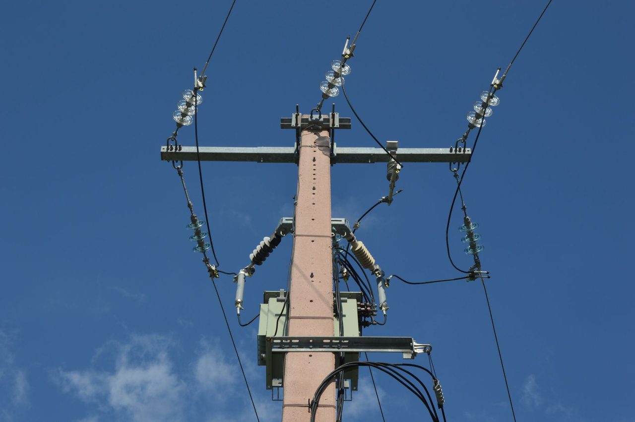
Photo: Ulrick Trappschuh on Pexels
India’s renewable buildout in 2026 is no longer constrained only by generation economics. For many solar, wind, hybrid and RTC projects, the bigger execution risk sits inside the evacuation system: the substation busbar scheme. Developers often spend months on land, modules, turbines, BESS sizing and connectivity approvals, but treat the bus arrangement as a standard engineering detail. It is not. The difference between single bus, double bus, breaker-and-a-half or ring bus can materially change outage risk, maintainability, grid-code compliance, future bay expansion and lender comfort.
For ISTS-connected renewable projects, pooling substations, GEC-linked nodes and large intra-state evacuation hubs, the busbar choice has become a board-level engineering and financing decision. In 2026, with tighter commissioning windows, more stringent availability expectations and increasing scrutiny from CTUIL, STUs, RLDCs and lenders, substation topology must be selected on lifecycle value, not only initial CAPEX.
This article explains how busbar schemes are evaluated for Indian renewable evacuation projects, what they cost in broad 2026 terms, where each scheme fits, and how to avoid expensive redesigns after connectivity has been granted.
Why busbar topology matters more in 2026
India’s transmission environment has changed sharply over the last three years:
- Larger solar parks are being connected at 220 kV, 400 kV and in some cases through pooling arrangements linked to 765 kV ISTS systems.
- Wind-rich states such as Gujarat, Tamil Nadu, Rajasthan and Karnataka are seeing multi-developer evacuation nodes where outage coordination is complex.
- Hybrid and FDRE/RTC projects are raising the utilisation factor of evacuation assets, which reduces tolerance for planned shutdowns.
- BESS is being added at pooling and grid substations, increasing switching complexity and fault contribution behaviour.
- Grid-code compliance expectations on fault ride-through, voltage support and disturbance performance are higher than in earlier solar-only deployments.
In that context, the substation busbar arrangement determines three commercially critical outcomes:
- How much generation is lost when a bus fault, breaker failure or maintenance outage occurs
- How easily future line, transformer or reactor bays can be added
- Whether scheduled and forced outages can be managed without breaching PPA availability assumptions
A poor scheme can save a few crore upfront and then cost much more through curtailment, outage coordination, liquidated damages, redesign and higher O&M complexity.
The main busbar schemes used in Indian RE evacuation substations
For renewable evacuation, the most relevant configurations in 2026 are these:
- Single bus single breaker
- Sectionalised single bus
- Main and transfer bus
- Double bus single breaker
- Ring bus
- Breaker-and-a-half
Each has a different position on the CAPEX-reliability-flexibility curve.
Single bus single breaker is the simplest and lowest-cost layout. It is still used for smaller radial evacuation substations, captive and C&I projects, and some intra-state nodes where outage consequences are manageable. But for large RE pooling with multi-hundred-MW evacuation, it is often too fragile. A bus fault can shut down the entire station section. Planned maintenance can also become highly restrictive.
Sectionalised single bus improves matters modestly by splitting the bus with a bus coupler or sectionaliser. This reduces the extent of outage for some contingencies and can be useful where budget is tight but total station shutdown risk must be reduced.
Main and transfer bus is common in conventional utility practice because it allows maintenance flexibility using isolators and transfer arrangements. However, in fast-changing RE substations, developers must carefully assess whether the operational complexity and switching philosophy align with staffing and remote-operation capability.
Double bus single breaker offers better flexibility. Bays can be shifted between buses, maintenance is easier, and bus faults affect a smaller operational envelope if configured correctly. It is often a practical middle ground for 220 kV and 400 kV renewable pooling substations.
Ring bus provides strong reliability for a moderate-to-high CAPEX increment. Each circuit is connected between two breakers in a ring, allowing one breaker to be maintained without total bay outage. It suits substations with a limited but important number of circuits.
Breaker-and-a-half is the premium topology for highly critical EHV substations. It offers excellent reliability and operational flexibility. In stations evacuating large quantum to ISTS, especially where multiple generators, ICTs and transmission lines converge, this scheme significantly reduces outage exposure. The obvious drawback is cost, layout complexity and longer engineering time.
What Indian developers should compare before freezing the scheme
The busbar choice should not be made from a standard template or solely from a utility preference note. It should be based on project-specific technical and commercial questions.
First, assess consequence of outage in MW and revenue terms.
If a 300 MW solar plant on a radial 220 kV line loses one full day due to bus maintenance, the energy loss at a 26% CUF is about 1.87 million units. At a realised tariff of Rs 2.90 per kWh, that is roughly Rs 54 lakh of top-line impact for one day. For a 1 GW hybrid node with higher utilisation, outage cost is much larger. Once this arithmetic is visible, a higher-CAPEX bus scheme often becomes easier to justify.
Second, examine future bay addition certainty.
Many substations are initially sanctioned with a limited number of line and transformer bays, then expanded as adjoining phases or third-party injections materialise. If the station is likely to add:
- a second ICT
- n- additional line bays
- reactor bays
- BESS feeders
- hybrid pooling feeders
then topology flexibility matters. Retrofitting a constrained bus arrangement later is often expensive and outage-intensive.
Third, align with connectivity conditions and utility practice.
CTUIL, the concerned STU, and the substation owner’s engineering standards may effectively narrow the topology options. For ISTS-linked projects, bay interface, protection philosophy, breaker failure logic, metering arrangement and bus differential requirements must all be checked early. This is where detailed Power system studies and primary engineering need to move in parallel, not sequentially.
Fourth, consider maintainability under Indian site conditions.
Dust, heat, monsoon constraints, spares availability and local O&M capability all affect real-world reliability. A theoretically elegant scheme with high switching complexity may underperform if field execution, interlocking logic or SCADA visibility is weak.
Fifth, factor lender and insurer scrutiny.
For large financed assets, lenders increasingly ask whether a single point of failure can trip disproportionate generation. A more resilient bus scheme can support due diligence conclusions on evacuation robustness, especially for multi-source hybrid projects with tight debt-service assumptions.
2026 cost ranges: what the busbar choice does to CAPEX
Exact numbers depend on voltage level, bay count, insulation technology, utility standards, land cost and OEM selection. But broad 2026 market ranges in India are directionally useful.
At 220 kV level, moving from a basic single-bus arrangement to a double-bus or ring-bus configuration can increase switchyard CAPEX by roughly 10% to 25% for a moderate bay count. The increment comes from additional breakers, isolators, bus PT/CVT arrangements, protection panels, control wiring, structures and larger yard footprint in AIS layouts.
At 400 kV level, the absolute impact is sharper. Upgrading from a lower-redundancy scheme to breaker-and-a-half can add several crore rupees depending on the number of line and transformer bays. In 2026 pricing terms, one extra 400 kV breaker bay package with associated equipment, civil works, protection and integration can easily move the budget by Rs 4 crore to Rs 8 crore or more, depending on specification and site conditions. For GIS-based solutions, the premium can be higher in equipment terms, though footprint savings may offset some land and constructability constraints.
Developers should also remember the hidden costs of minimalist schemes:
- Longer planned outages during expansion
- Higher curtailment risk during breaker maintenance
- Greater exposure to common-mode bus faults
- More difficult commissioning sequencing when multiple packages overlap
- Potential redesign after utility review
In many cases, spending an additional 2% to 5% at total evacuation-package level can reduce much larger lifetime revenue risk.
Scheme selection by project type: what usually makes sense
There is no universal answer, but some 2026 patterns are clear.
For small captive or C&I open-access projects, especially below about 50 MW with simple evacuation, a sectionalised single bus at 132 kV or 220 kV may be adequate if utility outage windows are manageable and future expansion is limited.
For utility-scale solar projects in the 100 MW to 300 MW range connecting at 220 kV, the decision often sits between sectionalised single bus, main and transfer bus, and double bus single breaker. If the project is in a congested RE zone or likely to expand, double bus often provides a better lifecycle outcome.
For large solar-wind hybrid parks, developer pooling stations and nodes feeding ISTS, ring bus or double bus at 220 kV/400 kV is frequently justified. The stronger the revenue dependence on continuous evacuation, the harder it is to defend a low-redundancy arrangement.
For ultra-large pooling substations, critical 400 kV injection points, and substations expected to evolve into shared evacuation infrastructure, breaker-and-a-half deserves serious consideration from day one. It is not overengineering when outage cost is high and bay growth is likely.
For substations with severe land constraints, GIS may be paired with higher-reliability bus schemes despite higher equipment cost. Here the right decision cannot be made without integrated HV/EHV substation design and lifecycle OPEX review.
Protection, operations and compliance implications
Busbar topology is not only a primary-equipment decision. It changes protection and operations philosophy materially.
A more complex bus arrangement requires:
- Robust busbar differential protection zones
- Breaker failure protection with correct logic selectivity
- Interlocking philosophy aligned with transfer and maintenance modes
- SCADA and event-logging clarity for remote operations
- Synchronisation and switching procedures that operators can execute safely
This is why topology selection should be coordinated with Protection, control & SCADA engineering from the concept stage. Too often, developers finalise the single-line diagram and only later discover that panel count, control-room space, cable quantities and integration effort have all been underestimated.
From a compliance perspective, a resilient substation scheme also supports better disturbance performance. While topology alone does not guarantee grid-code compliance, it can reduce the likelihood that a non-critical maintenance activity cascades into large evacuation loss. Utilities and load dispatch centres increasingly value designs that are operationally transparent and contingency-tolerant.
A practical decision framework for developers and lenders
Before freezing the substation single-line diagram, ask these questions:
- What is the maximum MW at risk for a bus fault?
- How many annual maintenance outages will require bay or bus shutdown?
- Is the station expected to add new feeders, ICTs, reactors or BESS later?
- What is the cost of one day of lost generation at expected CUF and tariff?
- Does the selected scheme align with CTUIL/STU and substation-owner standards?
- Can the O&M team safely operate the switching philosophy?
- How does the topology affect commissioning sequence and shutdown planning?
- Has the lender technical advisor reviewed common-mode outage exposure?
If these questions are answered quantitatively, the “cheapest scheme” often stops looking cheapest.
For example, assume a 500 MW hybrid project with effective annual utilisation above 35% and average realised revenue of Rs 3.20 per kWh. One full day of total evacuation loss can mean roughly 4.2 million units not delivered, or around Rs 1.34 crore of revenue impact. Two or three such events across the asset life can justify a significant share of the additional busbar CAPEX.
This is the right way to view the decision in 2026: not as an equipment upgrade, but as outage-risk pricing.
What is changing in procurement and execution in 2026
Two market developments are influencing substation bus decisions this year.
First, EPC timelines are tighter. Developers trying to save engineering time by copying an old substation scheme often face downstream approval delays when the connectivity context is different. Standardisation helps, but blind standardisation hurts.
Second, OEM and contractor capability varies significantly for advanced bus arrangements. Ring bus and breaker-and-a-half schemes need stronger detailed engineering, bay-wise outage planning, testing discipline and commissioning controls. Selecting a low bid without verifying experience in EHV renewable substations is risky.
For many projects, the answer is not simply to choose the most sophisticated topology. It is to choose the least complex scheme that still meets outage-risk, expansion and compliance requirements. That requires integrated planning across connectivity approvals, evacuation studies, primary design, protection philosophy, construction sequencing and O&M readiness.
Developers, C&I buyers evaluating supply reliability, lenders financing large RE portfolios, and utilities planning shared evacuation nodes should all treat busbar selection as a first-order bankability variable in 2026.
If you are evaluating a new pooling substation, an ISTS interconnection, or an expansion of an existing renewable evacuation node, Growthifye’s advisory desk can help with scheme selection, lifecycle cost comparison, Power system studies and HV/EHV substation design. Contact Growthifye to review your evacuation concept before the SLD is frozen.
Explore Growthifye's related capabilities
This analysis connects directly to our advisory practice: Power system studies · HV/EHV substation design · Transmission line engineering · Protection, control & SCADA.
About the author

Chief Executive Officer, Growthifye — With over 23 years in management consulting, Sudarshan has taken businesses from concept to scale — building and scaling new-age digital and energy businesses.
- 23+ years in management consulting
- EY alumnus
- Led large-scale BESS programmes, capital raises and advisory mandates
Want this analysis applied to your project?
Talk to our team

